Tripp Lite B0930042E4U Quick Start Guide for B093-004-2E4U B093-008-2E4U B093- - Page 2
Package Includes, Hardware Assembly
 |
View all Tripp Lite B0930042E4U manuals
Add to My Manuals
Save this manual to your list of manuals |
Page 2 highlights
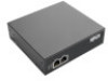
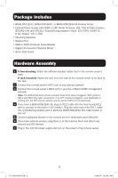
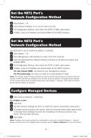
Package Includes • B093-004-2E4U, B093-008-2E4U, or B093-008-2E4U-M Console Server • External Power Supply with NEMA 1-15P (North America), CEE 7/16 Schuko (Europe), BS1363 (UK) and AS2112 (Australia) plug adapters (Input: 100-240V, 50/60 Hz, 0.4A; Output: 12V 1.25A) • Mounting Hardware • Rubber Feet • DB9-to-RJ45 Crossover Serial Adapter • Digital I/O Converter (Terminal Block) • Quick Start Guide Hardware Assembly 1 If free-standing: Attach the adhesive-backed rubber feet to the console server's base. If rack-mounted: Attach the rack kit to the side of the console server to be fixed to the rack. 2 Connect the console server's NET1 port to your primary network. 3 Connect the console server's NET2 port to your Out-of-Band (OOB) management network. Note: The B093-008-2E4U-M also includes Small Form-Factor Pluggable (SFP) ports for NET1 and NET2 fiber-optic connections. If an SFP module is plugged in and establishes a working link, the SFP port will activate and the paired RJ45 port will deactivate. 4 If you have a B093-008-2E4U-M, plug an RJ11 cable into the front-facing RJ11 port to connect to the built-in V.92 modem. Plug the other end of the RJ11 cable into a functioning landline port to allow the B093-008-2E4U-M's V.92 modem to dial-out 5 Connect additional devices to the console server's serial ports and USB ports. 6 If you have external sensors, plug them in to the terminal block and attach any sensors and DIO devices. 7 Plug in the 12V DC power supply and turn on the power to the console server. 2 17-12-034-933787.indb 2 12/8/2017 10:03:41 AM
-
 1
1 -
 2
2 -
 3
3 -
 4
4 -
 5
5 -
 6
6 -
 7
7 -
 8
8 -
9
-
10
-
11
-
12
-
13
-
14
-
15
-
16
-
17
-
18
-
19
-
20
 |
 |
