Tripp Lite PDUMNH30AT2 Automatic Transfer Switch PDU PDUMH30AT PDUMH30ATNET PD - Page 14
Network Management Card PDUMH30ATNET, PDUMNH30AT2
 |
View all Tripp Lite PDUMNH30AT2 manuals
Add to My Manuals
Save this manual to your list of manuals |
Page 14 highlights
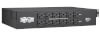
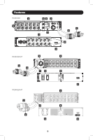
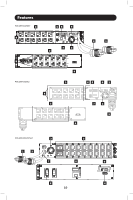
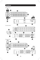
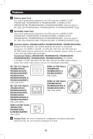
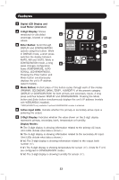
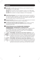
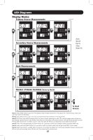
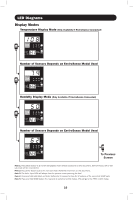
Features F Units LEDs: The AMPS, KW and VOLT LEDs are used to illustrate the units of data displayed on the 3-digit display. Amp LED: When selected, the load is displayed in amps on the 3-digit display. kW LED: When selected, the load is displayed in kilowatts on the 3-digit display. Volt LED: When selected, the voltage is displayed on the 3-digit display. 6 Output Circuit Breakers: Two circuit breakers protect equipment connected to each load bank against overloads. If a breaker trips, the circuit is overloaded and you need to reduce the load connected to the circuit breaker's load bank. Press the circuit breaker button to reset and restore power. 7 Ground Connection: Allows you to connect a user-supplied ground wire between the PDU and any equipment that requires a chassis ground. 8 Cord Retention Bracket (Optional Installation): When installed on the PDU, cord retention brackets provide secure attachment points for connected equipment power cords. 9 Network Management Card (PDUMH30ATNET, PDUMNH30AT2, PDUMH30HVATNET, PDUMNH30HVAT2, PDUMH32HVATNET, PDUMNH32HVAT2): The WEBCARDLX accessory allows you to operate the PDU as a managed network device, accessible via SNMP network management platform, web browser, SSH or telnet. For details, refer to the WEBCARDLX Owner's Manual included with this product. NOT SHOWN-C14 Plug-Lock Insert Sleeve (Optional): Use the included plastic sleeves to secure C13 power cords to C14 inlets. Fit the sleeve over the end of the cord, making sure the pull-tabs remain outside the cord and the fit is secure. To unplug equipment properly, grip both the cord and the insert's tabs at the same time and pull. NOT SHOWN-C20 Plug-Lock Insert Sleeve (Optional): Use the included plastic sleeves to secure C19 power cords to C20 inlets. Fit the sleeve over the end of the cord, making sure the pull-tabs remain outside the cord and the fit is secure. To unplug equipment properly, grip both the cord and the insert's tabs at the same time and pull. 14
-
 1
1 -
2
-
3
-
4
-
5
-
6
-
7
-
8
-
 9
9 -
 10
10 -
 11
11 -
 12
12 -
 13
13 -
 14
14 -
 15
15 -
 16
16 -
 17
17 -
 18
18 -
 19
19 -
20
-
21
-
22
-
23
-
24
-
25
-
26
-
27
-
28
-
29
-
30
-
31
-
32
-
33
-
34
-
35
-
36
-
37
-
38
-
39
-
40
-
41
-
42
-
43
-
44
-
45
-
46
-
47
-
48
-
49
-
50
-
51
-
52
-
53
-
54
-
55
-
56
-
57
-
58
-
59
-
60
-
61
-
62
-
63
-
64
-
65
-
66
-
67
-
68
-
69
-
70
-
71
-
72
-
73
-
74
-
75
-
76
-
77
-
78
-
79
-
80
-
81
-
82
-
83
-
84
-
85
-
86
-
87
-
88
 |
 |