Tripp Lite PDUMNV15LX Owner s Manual for Monitored Rack PDU & Switched Rac - Page 5
Networking the PDU, Dynamic IP Address Assignment
 |
View all Tripp Lite PDUMNV15LX manuals
Add to My Manuals
Save this manual to your list of manuals |
Page 5 highlights
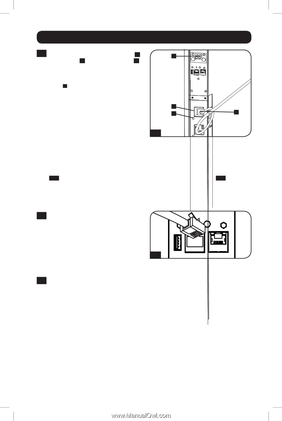
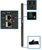
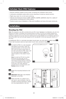
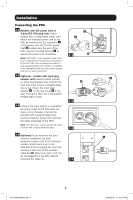
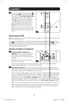
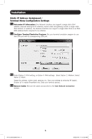
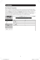
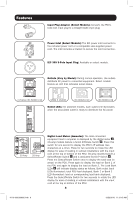
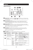
Installation 2-5 Connect your equipment's input plugs A D to the outlets B of the PDU. The LED C near each outlet (Switched Models Only) illuminates when the outlet is ready to distribute live AC power. The digital load meter D displays the total connected equipment load in amps. Select models provide additional load data. See the Features section for more information. B Note: In order to minimize interference among C A connected devices, connect each device to the nearest PDU outlet and coil excess power cord length. 2-5 Networking the PDU Note: The MAC address of the PDU (a 12-digit string in this format: 00 06 67 XX XX XX) is printed on a label attached to the PDU enclosure. If your network's DHCP server will assign a dynamic IP address to the PDU automatically, go to Step 3-1 . If you will assign a static IP address to the PDU manually, go to Step 4-1 . If you are uncertain which method to use, contact your network administrator for assistance before continuing the installation process. Dynamic IP Address Assignment 3-1 Connect Network Interface to Network: Connect a standard Ethernet patch cable to your network using the RJ45 Ethernet port on the PDU's Network Interface. Note: This port does not support PoE (Power over Ethernet) applications. 3-1 The interface will attempt to obtain an IP address via DHCP. This may take as long as several minutes, depending on your network environment. 3-2 Determine IP Address: To identify the IP address assigned to the Network Interface, contact your network administrator and provide the MAC address of the Network Interface. You can also determine the IP address locally at the card. Start a terminal emulation program, such as Tera Term Pro. Configure the COM port intended for use by following these settings: 115.2 Kbps, 8, NONE, 1. Using the included RJ45 to DB9 cable (part number 73-1243), connect your PC to the PDU's CONFIG port. When the login prompt appears, login as localadmin / localadmin. When the Menu appears, navigate to "3Network Configuration", then to "1- IP Configuration". The assigned IP address will be displayed. After you have determined the IP address, proceed to the Test Network Connection section. Note: You may wish to request a long-term lease period for the IP address, depending on your application. Note: PowerAlert Device Manager and the PDU's Network Interface support both IPv4 and IPv6. The card is set up by default to receive a DHCP address for IPv4, IPv6 or both. Receiving both addresses allows connection to the card via either the IPv4 or IPv6 address. 5 16-10-209-933666.indb 5 12/22/2016 11:31:35 AM
-
 1
1 -
 2
2 -
 3
3 -
 4
4 -
 5
5 -
 6
6 -
 7
7 -
 8
8 -
 9
9 -
 10
10 -
 11
11 -
12
-
13
-
14
-
15
-
16
-
17
-
18
-
19
-
20
-
21
-
22
-
23
-
24
-
25
-
26
-
27
-
28
-
29
-
30
-
31
-
32
-
33
-
34
-
35
-
36
 |
 |