Tripp Lite SMART1500LCD Owner's Manual for SMART1200LCD, SMART1500LCD & OM - Page 3
Basic Operation Front Panel, Basic Operation Rear Panel - replacement battery
 |
View all Tripp Lite SMART1500LCD manuals
Add to My Manuals
Save this manual to your list of manuals |
Page 3 highlights
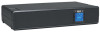
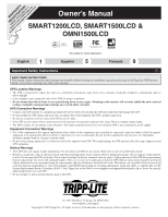
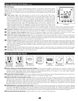
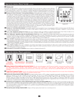
Basic Operation (Front Panel) continued 3 LCD Display The LCD Display indicates a variety of UPS operational conditions. All descriptions apply when the UPS is plugged into an AC outlet and turned on. The LCD Display can be rotated for easy viewing, regardless of whether the UPS is in a horizontal or vertical ("tower") position. To rotate the display, insert a small tool in the slots on the sides of the display to pop it out of the UPS housing; rotate the display, and snap it back into the UPS housing. 3a "Input Voltage" Meter: This meter measures, in real time, the AC voltage that the UPS system is 3a receiving from the utility wall outlet. Although the meter may occasionally display input voltages which stray (due to poor quality utility service) outside the range of standard computer tolerance, rest assured 3g 3b that the UPS is designed (through the use of automatic voltage regulation) to continuously supply connected equipment with stable, computer-grade output voltage. In the event of a blackout (power loss), severe brownout (low power) or overvoltage (high power), the UPS will rely on its internal battery to 3c 3d 3e 3f supply computer-grade output voltage. The Input Voltage Meter can be used as a diagnostic tool to 3 identify poor quality input power. By plugging the UPS into different outlets within a facility, you can identify individual circuits that are consistently providing low power, which can be caused by the LCD Display combined equipment load demanding more power than the circuit is designed to supply. If all circuits within a facility consistently provide low power, the facility may be served by inadequate utility service or may be in an industrial or commercial area with an overburdened power grid. 3b "BATTERY CAPACITY" Meter: This meter displays the approximate charge level (in 20% increments) of the UPS's internal battery. During a blackout or severe brownout, the UPS will switch to battery power, the "ON BAT" icon will be illuminated, and the charge level will deplete. 3c "AVR" (Automatic Voltage Regulation) Icon: This icon will illuminate whenever your UPS is automatically correcting low AC line voltage without depleting battery power. This is a normal, automatic operation of your UPS, and no action is required on your part. 3d "REPLACE" (Battery Recharge/Replace) Icon: This icon will illuminate and an alarm will sound after a self-test to indicate the UPS battery needs to be recharged or replaced. Allow the UPS to recharge continuously for 12 hours, and repeat the self-test. If the icon continues to illuminate, contact Tripp Lite for service. Battery replacement should only be performed by qualified service personnel. If the UPS requires battery replacement, Tripp Lite offers a complete line of replacement batteries at www.tripplite.com. 3e "ON BAT" (On Battery) Icon: During a severe brownout or blackout, this icon illuminates and an alarm sounds (4 short beeps followed by a pause) to indicate the UPS is operating from its internal batteries. Monitor the "Battery Capacity" Meter to determine the approximate battery charge level available to support equipment. During a prolonged brownout or blackout, the alarm will sound continuously (and the "BATTERY CAPACITY" Meter will show one 20% capacity segment shaded) to indicate the UPS's batteries are nearly out of power; you should save files and shut down your equipment immediately. 3f "FAULT" Icon: This icon will illuminate and an alarm will sound after a self-test to indicate the outlets are overloaded. To clear the overload, unplug some of your equipment from the outlets and run the self-test repeatedly until the icon is no longer illuminated and the alarm is no longer sounding. 3g LCD Dimmer: Adjusts the brightness of the LCD Status Screen. Basic Operation (Rear Panel) 4 Battery Backup Protected/Surge Protected Outlets 5 Surge-Only Protected Outlets (Select models only) 6 RS-232 Port (Select models only) 6 USB Port 7 Tel/DSL/ Network Jacks 8 9 Removabe Power Sensitivity Dial Mounting Hardware 4 Battery Backup Protected/Surge Protected Outlets: Provide connected equipment with AC line power (backed by surge protection and line noise filtering) during normal operation. Automatic voltage regulation continually corrects brownout (low voltage) and high voltage conditions without using battery power. Provide battery power during blackouts and severe brownout or severe high voltage conditions. DO NOT PLUG LASER PRINTERS INTO ANY OF THESE OUTLETS. 5 Surge-Only Protected Outlets: Provide surge and line noise protection, but NOT battery backup. Plug equipment that does not require battery backup during a utility power failure (such as printers, scanners or fax machines) into these outlets. 6 USB and RS-232 Communication Ports: These ports can connect your UPS to any computer for automatic file saves and unattended shutdown in the event of a power failure. Use with Tripp Lite's PowerAlert Software (available as a FREE download at www.tripplite.com) and appropriate USB or DB9 cable. A USB or DB9 cable may be included with your UPS. If the appropriate cable did not come with your UPS, any user-supplied DB9 pass-through or USB cable may then be used to connect your UPS to your computer. Note: This connection is optional. The UPS will work properly without this connection. Also Note: This UPS System provides basic communication compatibility with most integrated Windows®, Macintosh® and Linux® power management applications. 7 Tel/DSL/Network Line Surge Protection Jacks: Your UPS has jacks that protect against surges on a single phone, fax, modem or Ethernet network line. Using appropriate telephone or network cords connect your wall jack to the UPS jack marked "IN." Connect your equipment to the UPS jack marked "OUT." Make sure the equipment you connect to the UPS's jacks is also protected against surges on the AC line. Connecting your equipment to these jacks is optional. Your UPS will work properly without this connection. Not compatible with PoE (Power Over Ethernet) applications. 8 Removable Mounting Hardware: Adapts the UPS to either tower or rackmount (2U) applications. 3
-
 1
1 -
 2
2 -
 3
3 -
 4
4 -
 5
5 -
 6
6 -
 7
7 -
 8
8 -
 9
9 -
10
-
11
-
12
 |
 |