Tripp Lite SMART500RT1U Owner's Manual for SmartPro Rackmount UPS 932406 - Page 6
Optional Installation - tripp lite
 |
View all Tripp Lite SMART500RT1U manuals
Add to My Manuals
Save this manual to your list of manuals |
Page 6 highlights
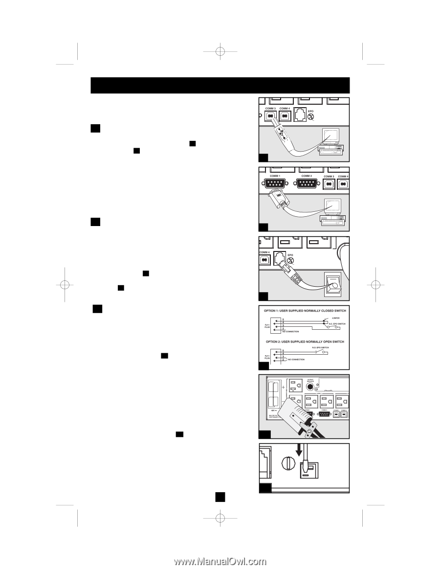
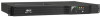
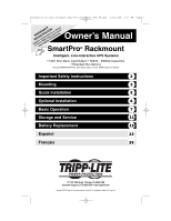
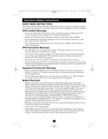
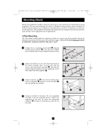
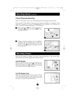
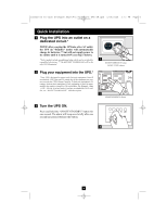
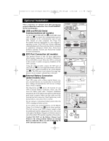
200503166 93-2406 Sinewave SmartPro Rackmount UPS OM.qxd 3/29/2005 3:12 PM Page 6 Optional Installation These connections are optional. Your UPS will function properly without these connections. Note: SMART3000RM2U shown in all diagrams. 1 USB and RS-232 Serial Communications (all models) Use the included USB cable (see 1a ) and/or DB9 serial cable (see 1b ) to connect the communication port on your computer to the communication port of your 1a UPS. Install on your computer the Tripp Lite PowerAlert Software appropriate to your computer's operating system. Your UPS may feature additional communications ports; these ports may also be connected to additional computers which have PowerAlert Software installed. Consult your PowerAlert manual for more information. 2 EPO Port Connection (all models) This optional feature is only for those applications 1b which require connection to a facility's Emergency Power Off (EPO) circuit. When the UPS is connected to this circuit, it enables emergency shutdown of the UPS's inverter. Using the cable provided, connect the EPO port of your UPS (see 2a ) to a user-supplied normally closed or normally open switch according to the circuit diagram (see 2b ). The EPO port is not a phone line surge sup- pressor; do not connect a phone line to this port. 2a 3 External Battery Connection (select models only) 4-5 Your UPS comes with a robust internal battery sys- tem; external batteries are needed only to extend run- time. Adding external batteries will increase recharge time as well as runtime. The illustration (see 3a ) shows the location of your UPS's External Battery Connector, where you will 2b insert the battery pack cable. Complete installation instructions for your battery pack appear in the battery pack owner's manual. Make sure that cables are fully inserted into their connectors. Small sparks may result during battery connection; this is normal. Do not connect or disconnect battery packs when the UPS is running on battery power. If you connect any external batteries, set the Battery Charge Level Switch (see 3b ) to the down position. 3a This will increase your UPS's charger output so that the additional batteries charge faster. Note: The switch to the right of the Battery Charge Level Switch is inactive and will not affect UPS operation regardless of its position. Caution! DO NOT set the Battery Charge Level Switch to the down position without an external battery connected. There is a risk of damaging the 3b UPS's internal battery system. 6
-
 1
1 -
 2
2 -
 3
3 -
 4
4 -
 5
5 -
 6
6 -
 7
7 -
 8
8 -
 9
9 -
 10
10 -
 11
11 -
 12
12 -
13
-
14
-
15
-
16
-
17
-
18
-
19
-
20
-
21
-
22
-
23
-
24
-
25
-
26
-
27
-
28
-
29
-
30
-
31
-
32
-
33
-
34
-
35
-
36
 |
 |