Tripp Lite SU12000RT4UPM Owner's Manual for Hot Swappable Modular UPS 932676 - Page 5
Detachable Power Distribution Unit PDU
 |
View all Tripp Lite SU12000RT4UPM manuals
Add to My Manuals
Save this manual to your list of manuals |
Page 5 highlights
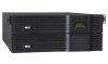
Features (continued) Detachable Power Distribution Unit (PDU) This independent, detachable PDU houses the UPS system's AC power input/output connections and a manual bypass switch. While the manual bypass switch is set to BYPASS, the PDU can be removed from the power module for routine power module maintenance, repair or replacement without interrupting the flow of power to connected equipment loads. Connected equipment will receive unfiltered AC utility line power while the switch is set to BYPASS, but the equipment will not receive battery power in the event of a power failure. See the "Manual Bypass Procedure" section for detailed manual bypass instructions. An optional PDU with hardwire output is also available from Tripp Lite. Call (773) 869-1234 or go to www.tripplite.com for more information on available PDU options. Reverse View 9 12 Top View 10 13 11 11 8A 9 8B 8B 9 8C 8 AC Output Receptacles (Outlets): 8A These IEC-320-C19 outlets accept IEC-320-C20 plugs. 8B These NEMA 5-15/20R outlets accept NEMA 5-15P or NEMA 5-20P plugs. 8C These NEMA L6-30R outlets accept NEMA L6-30P plugs. 9 AC Output Breakers: These breakers prevent the AC output receptacles from operating when they are overloaded. If the breakers trip during an overload, they may be reset to continue normal operation after the overload has been corrected by removing excess equipment loads. 10 Manual Bypass Switch: When this switch is set to BYPASS, qualified service personnel may detach the PDU to allow power module maintenance, repair or replacement without interrupting the flow of power to connected equipment loads. Connected equipment will receive unfiltered AC utility line power while the switch is set to BYPASS, but the equipment will not receive battery power in the event of a power failure. See the "Manual Bypass Procedure" section for detailed manual bypass instructions, including important safety warnings. WARNING! The manual bypass switch is for use by qualified personnel only. Unless the complete bypass procedure is performed correctly, the UPS will not be adequately powered down, presenting a risk of death or serious injury from contact with high voltage. 11 Utility Input Terminal Block: Use these terminals to connect the PDU to AC utility input power. To access the terminals, unscrew and remove the terminal block cover. (Diagram shows cover removed.) The UPS must be connected to a dedicated circuit of sufficient amperage, split-phase rated in accordance with the equipment nameplate and properly grounded. Connect the UPS system only to a fourwire input power connection (L1, L2, N, G). The UPS requires an input neutral connection. 12 Power Module Terminal Block: These terminals connect the PDU to the Power Module's corresponding Input/Output Terminal Block. WARNING: Do not contact the live terminals. 13 Utility Input Terminal Block Cable Access: Route the AC utility input power cables through these knockouts in order to attach the cables to the Utility Input Terminal Block. 201102169 93-2676.indd 5 5 3/29/2011 5:08:16 PM
-
 1
1 -
 2
2 -
 3
3 -
 4
4 -
 5
5 -
 6
6 -
 7
7 -
 8
8 -
 9
9 -
 10
10 -
 11
11 -
12
-
13
-
14
-
15
-
16
-
17
-
18
-
19
-
20
-
21
-
22
-
23
-
24
-
25
-
26
-
27
-
28
-
29
-
30
-
31
-
32
-
33
-
34
-
35
-
36
-
37
-
38
-
39
-
40
-
41
-
42
-
43
-
44
-
45
-
46
-
47
-
48
-
49
-
50
-
51
-
52
-
53
-
54
-
55
-
56
 |
 |
