Troy-Bilt Big Red Technical Manual
Troy-Bilt Big Red Manual
 |
View all Troy-Bilt Big Red manuals
Add to My Manuals
Save this manual to your list of manuals |
Troy-Bilt Big Red manual content summary:
- Troy-Bilt Big Red | Technical Manual - Page 1
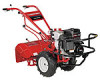
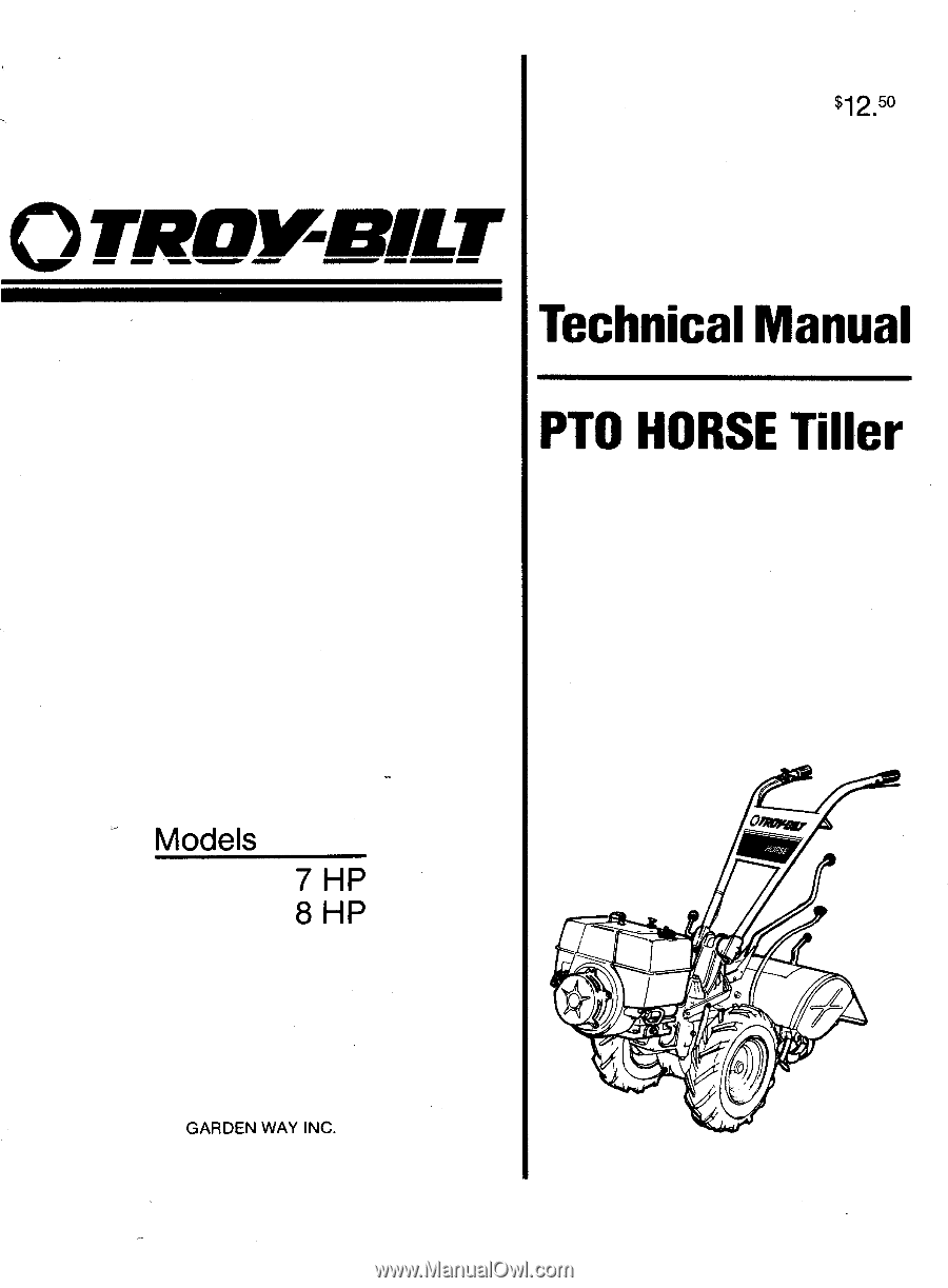
$12.50 OTP0111-113ILT Technical Manual PTO HORSE Tiller Models 7 HP 8 HP GARDEN WAY INC. a°w - Troy-Bilt Big Red | Technical Manual - Page 2
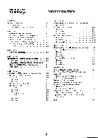
Tiller Tine Shaft Assembly Removal Inspection Installation SECTION 7. Special Repairs and Procedures Installing a New Tines/PTO Clutch Lever Assembly Removing the Existing Assembly Installing a New Assembly Removing a Rusted Wheel Removing the Wheel Shaft Without Disassembling the Transmission - Troy-Bilt Big Red | Technical Manual - Page 3
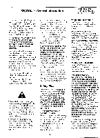
parts when the engine is running. AVOID ACCIDENTAL STARTING! When servicing the machine, prevent unintentional starting of the engine by disconnecting the spark plug wire and keeping the wire away from the spark plug. Place engine controls in the OFF position and shift the Wheels/ Tines/PTO Drive - Troy-Bilt Big Red | Technical Manual - Page 4
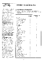
Oil Drain Plug Oil (Engine and Transmission) Oil Level Check Plug Pinion Shaft Pinion Shaft Gears PTO Power Unit Reverse Disc Solenoid Throttle Cable Tiller Attachment Tiller Drive Shaft Tiller Housing Cover Tiller Tine Shaft Tines/PTO Clutch Lever Tires/Wheels Transmission Pulley Wheel Shaft Wheel - Troy-Bilt Big Red | Technical Manual - Page 5
belt. See the Owner/Operator Manual for instructions. Tiller stays in reverse when the Wheels/Tines/PTO Lever is released. • Lubricate the motor mount bars, belt adjustment block, and linkages on the lever. See the Owner/Operator Manual for instructions. • Check the adjustment of the reverse disc - Troy-Bilt Big Red | Technical Manual - Page 6
PTO HORSE MODEL TECHNICAL MANUAL Page 2-2 4/90 SECTION 2: Transmission Troubleshooting Wheel Speed Shifting Problems Symptom Wheel Speed Lever drops out of fast speed. Wheel Speed Lever hard to shift. Wheel Speed Lever moves into slow speed but not into fast. Wheel Speed Lever moves freely but - Troy-Bilt Big Red | Technical Manual - Page 7
the clutch into either gear. Remedy • Inspect the drive belt for wear or mis-adjustment. See the Owner/Operator Manual for instructions. • Check condition and adjustment of reverse disc. See the Owner/Operator Manual for instructions. • Inspect the mounting bolt on the transmission drive pulley. It - Troy-Bilt Big Red | Technical Manual - Page 8
PTO HORSE MODEL TECHNICAL MANUAL Page 2-4 4/90 SECTION 2: Transmission Troubleshooting Wheels and/or Tines Do Not Turn Symptom Wheels turn but the tines do not. Remedy • Make sure the Tines/PTO Clutch Lever is engaged. • Adjust the Tines/PTO Clutch Lever. • Make sure the power unit or tiller - Troy-Bilt Big Red | Technical Manual - Page 9
Troubleshooting PTO HORSE MODEL TECHNICAL MANUAL Page 2-5 4/90 Oil Leaks Symptom Oil leaks from the wheel shaft oil seals. Oil leaks from the rear of the tiller attachment housing. Remedy • An oil seal is worn or damaged. Check for side-to-side and vertical play in the wheel shaft and replace - Troy-Bilt Big Red | Technical Manual - Page 10
PTO HORSE MODEL TECHNICAL MANUAL Page 2-6 4/90 SECTION 2: Transmission Trouleshooting Oil Leaks Symptom Remedy Oil leaks from the front oil seal on the power unit drive shaft. Oil could appear in the base of the motor mount under the pulley. (Make sure this is not an oil leak from the - Troy-Bilt Big Red | Technical Manual - Page 11
spark plug. Place the engine throttle control in the OFF position and shift the Wheels/Tines/PTO Drive Lever into NEUTRAL. PTO Power Unit Drive Shaft Pulley- Check the PTO drive shaft pulley (see Figure 3-2) for end play and oil leaks: 111 Drive Shaft Pulley Figure 3-2: Pre-Disassembly Inspection - Troy-Bilt Big Red | Technical Manual - Page 12
be installed on the tiller tine shaft, as explained in Section 6 of this manual. PTO Power Unit and Tiller Attachment Drive Shaft Connection - Engage the Tines/ PTO Clutch Lever and turn the pulley at the front of the PTO power unit. The dog clutches between the tiller attachment and the PTO power - Troy-Bilt Big Red | Technical Manual - Page 13
Attachment transmission needs to be removed from the tiller, refer to the Owner/Operator Manual for instructions on how to remove the transmission when the tiller is fully assembled. A WARNING: When servicing the machine, prevent unintentional starting of the engine by disconnecting the spark plug - Troy-Bilt Big Red | Technical Manual - Page 14
Tines/PTO Clutch Lever detent shifting plate (15). 18. Remove the wheels from the wheel shaft. See the Owner/Operator Manual for instructions. Or, if the wheel is rusted on the shaft, see "Removing a Rusted Wheel" in Section 7 of this manual. Separating the Transmissions 1. Put the transmission (PTO - Troy-Bilt Big Red | Technical Manual - Page 15
Interlock Safety System" the PTO Horse Model Owner/Operator Manual. 20. For electric start tillers only: a. Attach the battery bracket to the transmission cover and attach the two mounting bolts and lock washers that secure the legs of the bracket. b. For Briggs & Stratton engines only: Connect the - Troy-Bilt Big Red | Technical Manual - Page 16
the ENGAGE or DISENGAGE position. 25. Install the drive belt on the engine and transmission pulleys and adjust the belt tension according to the directions found in the Owner/Operator Manual. 26. Check the operation of the Wheels/Tines/PTO Lever by shifting it into Forward, then Neutral and Reverse - Troy-Bilt Big Red | Technical Manual - Page 17
PTO Horse Model Power Unit Transmission. A WARNING: When servicing the machine, prevent unintentional starting of the engine by disconnecting the spark plug wire and keeping the wire away from the spark plug. Place the engine throttle control in the OFF position and shift the Wheels/Tines/PTO Drive - Troy-Bilt Big Red | Technical Manual - Page 18
PTO HORSE MODEL TECHNICAL MANUAL Page 5-2 4/90 SECTION 5: PTO Power Unit Transmission Inspection These instructions describe how to inspect vital parts on the PTO power unit housing cover. In addition to inspecting the parts you have removed, you should also inspect any replacement parts. Note: - Troy-Bilt Big Red | Technical Manual - Page 19
own part number and requires specific related parts. Before installing a new drive shaft or related drive shaft parts, first determine which type of shaft you are working with. See the tiller parts catalog for parts ordering information. Removal 1. Remove the bolt (1) that holds the Tines/PTO Clutch - Troy-Bilt Big Red | Technical Manual - Page 20
attachment. After removing the bearings, remove the shoulder washers (22), if so equipped. Inspection These instructions describe how to inspect vital parts on the PTO power unit drive shaft. In addition to inspecting the parts you have removed, you should also inspect any replacement parts you will - Troy-Bilt Big Red | Technical Manual - Page 21
the tiller attachment sleeve. 20. Attach the Tines/PTO Clutch Lever (2) and finger tighten the bolt (1) that holds the lever. 21. Install the PTO power unit housing cover. See the instructions in this section. 22. Install the drive shaft pulley by reversing steps 5 and 6 of the drive shaft removal - Troy-Bilt Big Red | Technical Manual - Page 22
the fast speed gear. Inspection These instructions describe how to inspect vital parts on the pinion shaft assembly. In addition to inspecting the parts you have removed, you should also inspect any replacement parts you will use. (05 t 1 3 2 Figure 5-4: Pinion Shaft Assembly. 8 1 Figure 5-5: Stem - Troy-Bilt Big Red | Technical Manual - Page 23
Unit Transmission PTO HORSE MODEL TECHNICAL MANUAL Page 5-7 4/90 Note: Thoroughly degrease and clean all parts before inspection. Bearings - Hold the end of the stem pinion and spin the stem pinion bearing. If the bearing wobbles, or makes a growling noise, or cannot spin at all, replace the - Troy-Bilt Big Red | Technical Manual - Page 24
describe how to service the wheel shaft assembly. For instructions on how to remove the wheel shaft without disassembling the entire PTO power unit, see "Removing the Wheel Shaft Without Disassembling the Transmission" in Section 7. Use Figure 5-7 as a reference for part locations in these - Troy-Bilt Big Red | Technical Manual - Page 25
5: PTO Power Unit Transmission PTO HORSE MODEL TECHNICAL MANUAL Page 5-9 4/90 Removal Before you can service the wheel shaft assembly, you must first remove the pinion shaft assembly. See the pinion shaft removal instructions in this section. 1. Remove the left side oil seal (1). You can remove - Troy-Bilt Big Red | Technical Manual - Page 26
the fast speed gear and clutch. 7. Insert the wheel shaft through the right side and slip it through the gears and clutch. 8. Remove the piece of wood from the eccentric lever and check to make sure the eccentric shaft can move freely from side to side. 9. Using #30 weight oil, lubricate the bronze - Troy-Bilt Big Red | Technical Manual - Page 27
seal driver to install it flush with the transmission housing. 4. Start the spirol roll pin (2) in the eccentric lever (4) while the lever is still on the workbench. Then install the lever on the eccentric shaft. Make sure the lever is extended to the right side of the housing. 5. Install the wheel - Troy-Bilt Big Red | Technical Manual - Page 28
from the spark plug. Place the engine throttle control in the OFF position and shift the Wheels/Tines/PTO Drive Lever into NEUTRAL. Tiller Drive Shaft Assembly These instructions describe how to remove, inspect, and install the tiller attachment's drive shaft. Use Figure 6-1 as a reference for part - Troy-Bilt Big Red | Technical Manual - Page 29
to its bearing. 10. Remove the tiller tine shaft assembly. See the tiller tine shaft removal instructions in this section. You must remove the tiller tine shaft before you can completely remove the tiller drive shaft. 11. Remove the tiller drive shaft. 12. Remove the oil seal (13) by placing a long - Troy-Bilt Big Red | Technical Manual - Page 30
and install the tiller attachment's tine shaft assembly. Use Figure 6-2 as a reference for part locations in these instructions. Removal You will have to disassemble the tiller tine shaft assembly to replace a damaged worm gear, bearing, or shaft. Also, you will have to remove the tiller tine shaft - Troy-Bilt Big Red | Technical Manual - Page 31
SECTION 6: Tiller Attachment Transmission PTO HORSE MODEL TECHNICAL MANUAL Page 6-4 4/90 the Owner/Operator Manual for instructions on how to remove the bolo tine holders. 1. Remove the five bolts (1) and nylon washers (2), if any, that secure the tiller housing cover (3). Discard the washers. - Troy-Bilt Big Red | Technical Manual - Page 32
PTO HORSE MODEL TECHNICAL MANUAL Page 6-5 4/90 SECTION 6: Tiller Attachment Transmission b. Force the shaft down. This will dislodge one bearing (7). Also remove the washer (9), if so equipped. 10. Turn the shaft assembly 180 degrees and use the arbor press to dislodge the other bearing (and - Troy-Bilt Big Red | Technical Manual - Page 33
SECTION 6: Tiller Attachment Transmission PTO HORSE MODEL TECHNICAL MANUAL Page 6-6 4/90 are not sufficient, use two .030" gaskets, etc. until the shaft is shimmed correctly. Note: No more than .060" in total gasket thickness should be needed to correctly shim the tine shaft. Call the Troy-Bilt - Troy-Bilt Big Red | Technical Manual - Page 34
7: Special Repairs and Procedures Installing a New Tines/PTO /Clutch Lever Assembly In early model PTO Horse models, a ball bearing assembly on the Tines/PTO Clutch Shaft functioned as the contact piece that moved the PTO power unit dog clutch to engage the tiller attachment dog clutch. However - Troy-Bilt Big Red | Technical Manual - Page 35
tiller or disassemble the transmission. See Figure 7-2 as a reference for the part numbers in this section. Removal 1. Remove the oil drain plug and drain the transmission gear oil. Inspect the plug and if it is not damaged, replace it after the oil is drained. 2. Remove both wheels. See the Owner - Troy-Bilt Big Red | Technical Manual - Page 36
PTO HORSE MODEL TECHNICAL MANUAL Page 7-3 4/90 SECTION 7: Special Repairs and Procedures 11 10 14 16 / 15 12 13 XI 423 Figure 7-2: Wheel Shaft Assembly. 3. From the left side of the wheel shaft, remove the oil seal (1), the (external) snap ring (2), and the shim(s) (3). See Section 5 in - Troy-Bilt Big Red | Technical Manual - Page 37
SECTION 7: Special Repairs and Procedures PTO HORSE MODEL TECHNICAL MANUAL Page 7-4 4/90 Note: If necessary, you can remove the power unit housing cover to move the gear and clutch by hand. 8. Complete the installation of the wheel shaft. See Section 5 of this manual for more information. - Troy-Bilt Big Red | Technical Manual - Page 38
PTO power unit/tiller attachment.. .4-2 N Neutral plunger assembly Assembly. . .5-2 Disassembling. . .5-2 O Oil seal Removing Eccentric shaft. . .5-10 PTO drive shaft. . .5-3 Tiller drive shaft. . .6-2 Tiller tine shaft. . .6-4 Wheel shaft. . .5-9 Replacing Eccentric shaft. . .5-11 PTO drive shaft - Troy-Bilt Big Red | Technical Manual - Page 39
OT_Rownar TROY-BILT MANUFACTURING CO., 102nd Street & 9th Ave., Troy, New York 12180 Call Toll-Free: 1-800-833-6990 GARDEN WAY CANADA, INC., 1515• Matheson Blvd., Unit B11, Mississauga, Ontario L4W 2P5 Local calls only (416 Area Code): 624-8423 • From Ontario & Quebec Provinces call Toll-Free: 1-800
-
 1
1 -
 2
2 -
 3
3 -
 4
4 -
 5
5 -
 6
6 -
 7
7 -
8
-
9
-
10
-
11
-
12
-
13
-
14
-
15
-
16
-
17
-
18
-
19
-
20
-
21
-
22
-
23
-
24
-
25
-
26
-
27
-
28
-
29
-
30
-
31
-
32
-
33
-
34
-
35
-
36
-
37
-
38
-
39
 |
 |
$12.
50
OTP0111-113ILT
Technical
Manual
PTO
HORSE
Tiller
Models
7
HP
8
HP
GARDEN
WAY
INC.
a°w