Troy-Bilt Big Red Technical Manual - Page 19
Power, Drive, Shaft
 |
View all Troy-Bilt Big Red manuals
Add to My Manuals
Save this manual to your list of manuals |
Page 19 highlights
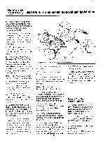
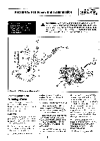
SECTION 5: PTO Power Unit Transmission PTO HORSE MODEL TECHNICAL MANUAL Page 5-3 4/90 PTO Power Unit Drive Shaft These instructions describe how to service the PTO power unit drive shaft. Before you can perform these instructions you must first remove the PTO power unit housing cover. See "PTO Power Unit Housing Cover" in this section for removal instructions. Use Figure 5-2 as a reference for part locations in these instructions. Note: Either of two basic types of drive shafts may have been installed at the factory: an integral worm design (worm is machined directly from the shaft material), or a welded worm design (the worm is welded to the shaft and can be identified by blue welds at either end of the worm). Each design has its own part number and requires specific related parts. Before installing a new drive shaft or related drive shaft parts, first determine which type of shaft you are working with. See the tiller parts catalog for parts ordering information. Removal 1. Remove the bolt (1) that holds the Tines/PTO Clutch Lever (2) to the clutch lever eccentric shaft (3). Then remove the lever from the shaft. 2. Loosen the hex nut/bushing (6) on the Tines/PTO Clutch Lever shaft and remove the remainder of the Tines/PTO Clutch Lever assembly (6-9). Observe the part of the lever (9) that engages the dog clutch (5). If it is excessively worn or damaged, or if the customer has had difficulty engaging the tiller attachment, replace the part with a newer-style socket head screw that is included with a complete conversion kit (Part No. 19 22 0 20 22 19 12 13 14 16 18 _nom I 20 15 213, 24 26 27 25 Figure 5-2: PTO Power Unit Drive Shaft. 1 4 21 11 10 0 10353). Refer to "Installing a New Tines/PTO Clutch Lever Assembly" in Section 7 of this manual. 3. Use snap ring pliers to remove the (external) snap ring (4) that retains the dog clutch (5) to the drive shaft (17). You will have to push in the dog clutch (5) to gain access to the snap ring. 4. Remove the dog clutch using a pair of needle nose pliers. Also make sure you retrieve the drive shaft key (10). 5. Remove the bolt (23) and concave washer (24) that hold the transmission pulley (25) to the drive shaft. 6. Remove the pulley and the drive shaft key (26). On welded drive shafts, remove the shoulder washer (27). 7. Remove the bolts (12) and lockwashers (13) that hold the front bearing cap (14). 8. Remove the front bearing cap. 9. Use an arbor press to remove the oil seal (15) from the front bearing cap. 10. Remove and discard the gasket (16) from the front bearing cap. 11. Pull the drive shaft (17) forward slightly just enough to dislodge the shims (18). Remove the shims. 12. Remove the front bearing cup (20) from the housing. Note: Keep each bearing cup paired with its bearing if you intend to reuse them. Each bearing cup wears differently according to its bearing. 13. Remove the drive shaft through the front of the transmission housing. 14. Insert a long bar in through the front of the transmission housing to knock out the rear oil seal (11). Be careful to not damage the inside of the housing, the bearing cup (20), or the retaining ring (21). 15. Put your hand down through the top of the housing and remove the rear bearing cup (20). If you
-
 1
1 -
2
-
3
-
4
-
5
-
6
-
7
-
8
-
9
-
10
-
11
-
12
-
13
-
 14
14 -
 15
15 -
 16
16 -
 17
17 -
 18
18 -
 19
19 -
 20
20 -
 21
21 -
 22
22 -
 23
23 -
 24
24 -
25
-
26
-
27
-
28
-
29
-
30
-
31
-
32
-
33
-
34
-
35
-
36
-
37
-
38
-
39
 |
 |
