Troy-Bilt Colt FT Operation Manual - Page 8
Adjustments
 |
View all Troy-Bilt Colt FT manuals
Add to My Manuals
Save this manual to your list of manuals |
Page 8 highlights
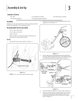
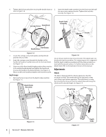
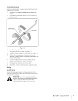
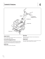
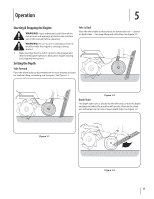
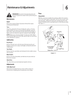
6. Tighten the bolt securely after securing the handle brace as 2. Insert the depth stake assembly into the frame and reinstall seen in Figure 1-4. the two screws removed earlier. Tighten the hex bolts securely. See Figure 1-6. Carriage Screw Hand Knob Depth Stake Assembly Screws Bell Washer Handle Brace Figure 1-4 7. Locate the carriage screw, bell washer and hand knob packed with your tiller. 8. Insert the carriage screw through the bracket on the handle, bell washer, handle brace and into the hand knob. See Figure 1-4. 9. Select one of the three handle height positions (three notches in the welded handle bracket) and tighten the hand knob to secure the handle in the desired position. See Figure 1-4. Return to the lower handle and tighten the hex bolt securely. Depth Gauge 1. Remove the two screws from the depth stake assembly. See Figure 1-5. Depth Stake Assembly Figure 1-6 Secure the pin with the clip removed earlier. The depth stake can be placed at various positions. For setup purposes it is suggested that the depth stake be assembled with the stake just above or level with the ground surface. For further instructions on the Depth Stake refer to the Operation Section of this manual. Adjustments Wheels The tiller is shipped with the wheels adjusted so that the machine sits level. The wheels need to be adjusted to meet your tilling needs before operation. This adjustment is made by removing the clevis pin from the wheel yoke and raising the wheels to the desired height. See Figure 1-7. Wheel Yoke Clevis Pin Screws Figure 1-5 8 Section 3- Assembly & Set-Up Cotter Pin Figure 1-7 Depth Stake
-
 1
1 -
2
-
 3
3 -
 4
4 -
 5
5 -
 6
6 -
 7
7 -
 8
8 -
 9
9 -
 10
10 -
 11
11 -
 12
12 -
 13
13 -
14
-
15
-
16
-
17
-
18
-
19
-
20
-
21
-
22
-
23
-
24
-
25
-
26
-
27
-
28
-
29
-
30
-
31
-
32
-
33
-
34
-
35
-
36
 |
 |
