URC MC-70VC Owners Manual - Page 5
MC-70VC Front, Bottom and Real Panel Descriptions
 |
View all URC MC-70VC manuals
Add to My Manuals
Save this manual to your list of manuals |
Page 5 highlights
MC-70VC INDOOR IP CAMERA MC-70VC Front, Bottom and Real Panel Descriptions Front View Mic Power LED Lens LAN LED Lens Guide Name Power LED LAN LED Lens Lens Guide MIC Description Red - Powered ON Green - Indicate a network connection Red - TX/RX Activity (Turned off when transmitting data.) Green - LINK (When cables are linked.) Lens for built-in Camera Used to adjust lens for better focus Audio Input Port Bottom View CTL LAN Power Connector Connector Jack Name CTL Connector LAN Connector Power Jack Description CTL Port (RS-232, DI, DO) RJ-45 Jack for Network Connection DC 12V Input from Power Adaptor Page 2
-
 1
1 -
 2
2 -
 3
3 -
 4
4 -
 5
5 -
 6
6 -
 7
7 -
 8
8 -
 9
9 -
 10
10 -
 11
11 -
12
 |
 |

Page 2
MC-70VC I
NDOOR
I
P
C
AMERA
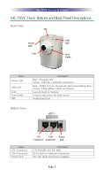
MC-70VC Front, Bottom and Real Panel Descriptions
Front View
Mic
Power
LED
Lens
LAN
LED
Lens
Guide
Name
Power LED
LAN LED
Lens
Lens Guide
MIC
Description
Red - Powered ON
Green - Indicate a network connection
Red - TX/RX Activity (Turned off when transmitting data.)
Green - LINK (When cables are linked.)
Lens for built-in Camera
Used to adjust lens for better focus
Audio Input Port
Name
CTL Connector
LAN Connector
Power Jack
Description
DC 12V Input from Power Adaptor
RJ-45 Jack for Network Connection
CTL Port (RS-232, DI, DO)
Bottom View
CTL
Connector
LAN
Connector
Power
Jack