URC MC-73CB Owners Manual - Page 5
Front View, Rear View
 |
View all URC MC-73CB manuals
Add to My Manuals
Save this manual to your list of manuals |
Page 5 highlights
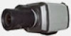
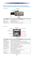
MC-73CB IP CAMERA MC-73CB Front and Rear Panel Descriptions Front View IRIS Connector Lens Mount Ring Name Lens Mount Ring Lens IRIS Connector Bracket Connector Lens Bracket Connector Description Adjustable hand-screw ring to mount the lens CS mount type Lens IRIS LENS Cable connector Screw Hole to Mount the camera to bracket Rear View LAN LED USB Connector Power LED LAN Connector Video Out CTL Connector Power Jack MIC Jack Factory Default Name Power Jack LAN (Tx/Rx) LED (ORANGE/GREEN) LAN Connector USB Connector POWER LED (RED/ORANGE) CTL Connector Video Out Factory Default MIC Jack Speaker Jack Speaker Jack Description DC 12V Input from Power Adaptor ORANGE - LAN TX/RX (Blinks when there is data activities) GREEN - LAN LINK (Turn on when physical LAN connection is made) RJ-45 Jack for network connection and power supply from PoE Switch Connector for WIFI USB Dongle RED - Light blinks when power is provided.) ORANGE - Light blinks when IP setup is done. Control Port (RS-485, RS-232, DI, DO) Video Out Connector Button to Set the Camera to Factory Default Values, DO NOT PRESS! Installer feature only The 3.5mm Jack Audio Input Port The 3.5mm Jack Audio Output Port Page 2
-
 1
1 -
 2
2 -
 3
3 -
 4
4 -
 5
5 -
 6
6 -
 7
7 -
 8
8 -
 9
9 -
 10
10 -
 11
11 -
12
 |
 |
