URC MC-75CD Owners Manual - Page 5
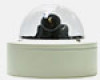
MC-75CD Front & Rear View under the Dome Cover
 |
View all URC MC-75CD manuals
Add to My Manuals
Save this manual to your list of manuals |
Page 5 highlights
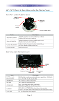
MC-75CD NETWORK CAMERA MC-75CD Front & Rear View under the Dome Cover Front View under the Dome Cover Adjust for Up /Down Adjust for Right/Left Camera Module Factory Default Switch Name Adjust for Up/Down Adjust for Right/Left Factory Default Switch Camera Module Description Adjust the position of camera module Up or Down (Needs to be fixed when installing) Adjust the position of camera module Right or Left (Needs to be fixed when installing) Button to Set the Camera to Factory Default Values, DO NOT PRESS! Installer feature only Board mount lens Rear View under the Dome Cover Name LAN Connector CTL Connector Speaker Jack MIC Jack POWER LED LAN LED Power Jack POWER Jack LAN CTL MIC Connector Connector Jack Speaker Jack POWER & LAN LED Description RJ-45 Jack for network connection and power supply from PoE Switch Control Port (RS-485, RS-232, DI, DO) The 3.5mm Jack Audio Output Port The 3.5mm Jack Audio Input Port RED - Light blinks when power is provided.) ORANGE - Light blinks when IP setup is done. ORANGE - LAN TX/RX (Blinks when there is data activities) GREEN - LAN LINK (Turn on when physical LAN connection is made) DC 12V Input from Power Adaptor Page 2
-
 1
1 -
 2
2 -
 3
3 -
 4
4 -
 5
5 -
 6
6 -
 7
7 -
 8
8 -
 9
9 -
 10
10 -
 11
11 -
12
 |
 |
