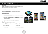
URC MRX-15 Owners Manual - Page 4
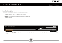
Rear Panel Description
 |
View all URC MRX-15 manuals
Add to My Manuals
Save this manual to your list of manuals |
Page 4 highlights
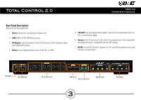
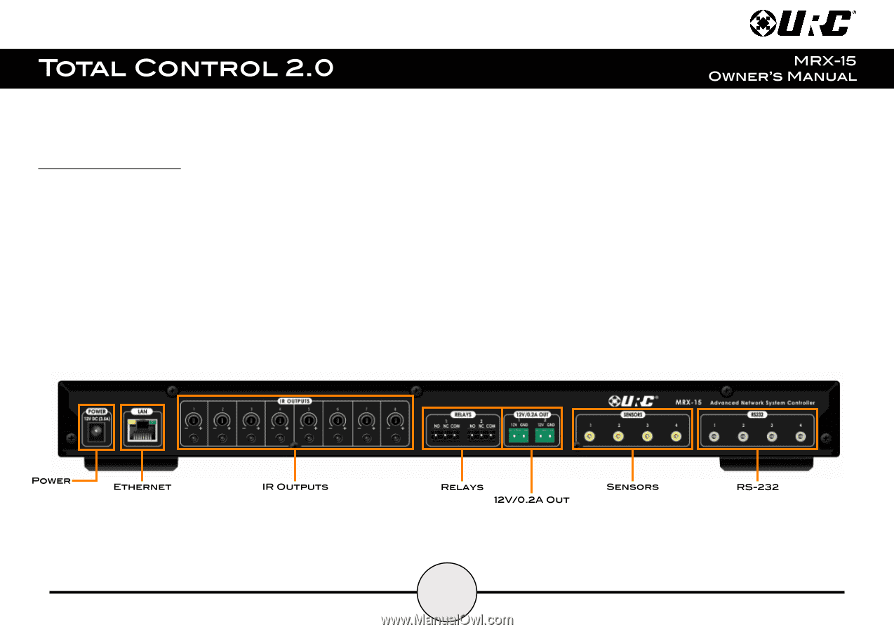
Rear Panel Description: Below are the rear panel ports: 1. Power: Attach the included power supply here. 2. LAN: RJ45 10/100/1000 Ethernet port. 3. IR Outputs: eight (8) standard 3.5mm IR emitter ports with individual output level adjustment screws. 4. Relays: two (2) programmable relays at NO, NC, or COM. 5. 12V OUT: two (2) programmable outputs. Each may be programmed to turn on, off, or momentarily toggle. 6. Sensors: four (4) sensor ports that allow the programming of state dependent and triggered macros. Compatible with all URC sensors. 7. RS232: four (4) RS-232 ports. Supports TX, RX, and GND connections for wired two-way communication. 3
-
 1
1 -
 2
2 -
 3
3 -
 4
4 -
 5
5 -
 6
6 -
 7
7 -
 8
8
 |
 |
Rear Panel Description:
Below are the rear panel ports:
1.
Power:
Attach the included power supply here.
2.
LAN:
RJ45 10/100/1000 Ethernet port.
3.
IR Outputs:
eight (8) standard 3.5mm IR emitter ports with individual output
level adjustment screws.
4.
Relays:
two (2) programmable relays at NO, NC, or COM.
5.
12V OUT:
two (2) programmable outputs. Each may be programmed to turn on,
off, or momentarily toggle.
6.
Sensors:
four (4) sensor ports that allow the programming of state dependent
and triggered macros. Compatible with all URC sensors.
7.
RS232:
four (4) RS-232 ports. Supports TX, RX, and GND connections for wired
two-way communication.
3