URC MSC-400 Owners Manual - Page 1
URC MSC-400 Manual
 |
View all URC MSC-400 manuals
Add to My Manuals
Save this manual to your list of manuals |
Page 1 highlights
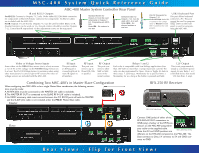
MSC-400 System Quick Reference Guide Power LED indicates that the MSC-400 is powered on. USB 1 LED indicates that the USB Programming Port (Front Panel USB) is connected to a PC. MSC-400 Master System Controller Front Panel Learning Sensor for learning IR commands. Normally, learning is more convenient via a remote. Status LED lights whenever an RF signal is received and UNDERSTOOD. USB 2 LED indicates that the USB PC Keyboard Port (Rear Panel USB) is connected to a PC. Notice to User This equipment has been tested and found to comply with the limits for a Class B digital device, pursuant to part 15 of the FCC Rules. These limits are designed to provide reasonable protection against harmful interference in a residential installation. This equipment generates, uses and can radiate radio frequency energy and, if not installed and used in accordance with the instructions, may cause harmful interference to radio communications. NOTE: MSC Editor Software is not included with the MSC-400. It can only be downloaded from the URC Dealer Only website. If you have not registered yet, call your distrib- utor or sales representative for a registration code and use the Dealer Login at: www.universalremote.com Sensor LEDs light when a Sensor is sensing that a component is ON (Video is present or Voltage is high). Front Panel USB port is used ONLY for PROGRAMMING However, there is no guarantee that interference will not occur in a particular installation. If this equipment does cause harmful interference to radio or television reception, which can be determined by turning the equipment off and on, the user is encouraged to try to correct the interference by one more of the following measures: Reorient or relocate the receiving antenna. Increase the separation between the equipment and receiver. Connect the equipment into an outlet on a circuit different from that to which the receiver is connected. Consult the dealer or an experienced radio/TV technician for help. RFX-250 Narrow Band RF Receiver Front Panel Start with the antenna angle set to 45 degrees and positioned so that the 45° long side of the antenna is facing the customer's favorite seating position. Warning Changes or modifications not expressly approved by the manufacturer could void the user's authority to operate the equipment. Note : The manufacturer is not responsible for any Radio or TV interference caused by unauthorized modifications to this equipment. Such modifications could void the user's authority to operate the equipment. Once the RFX-250 is correctly connected, the POWER LED lights. If the RF LED lights, the RFX250 must be moved to a new mounting location. It is receiving in-band RF INTERFERENCE. Front Views - Flip for Rear Views
-
 1
1 -
 2
2
 |
 |
