Vaddio Vaddio ClearVIEW HD-USB Vaddio ClearVIEW HD-USB Manual - Page 6
Connectors and Functions continued - ptz camera manual
 |
View all Vaddio Vaddio ClearVIEW HD-USB manuals
Add to My Manuals
Save this manual to your list of manuals |
Page 6 highlights
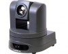
ClearVIEW HD-USB Conferencing Camera Connectors and Functions (continued) 5) YPbPr Output: Component HD video is fed through the DE-15 connector (HD-15 for the shell sized challenged). YPbPr and Composite signals are simultaneous. Note: This is an HD camera and the SD signals are down converted and are really not the sweet spot of this camera. This is a courtesy feature only. 6) Composite Video (CVBS) Output: The CVBS output feeds out SD video signals and is configurable with the dip switches to choose between 480i/NTSC or 576i/PAL in 4:3 formats. Squeeze and letterbox modes are also available (see dip switches). 7) EZ Power/Video Port: This RJ-45 connector is only used with the Quick-Connect SR Interface and the Quick-Connect DVI-D/HDMI SR Interface to supply power and return HSDS (high speed differential signaling) video from the camera. 8) 5 VDC Output: The 5 VDC output is on an EIAJ-03 connector was added to supply power to the active Extreme USB Extender transmitter side. The receiver side is powered by the computer's USB port or powered USB Hub. 9) USB 2.0 Connector: The USB 2.0 is on a Type-B female and attaches to a PC running a soft-client UC video conferencing system or video capture software that uses UVC (USB Video Class) standard drivers. No other drivers are required to plug the HD-USB into a computer and have it actually work. The UVC drivers will auto negotiate the highest resolution that the PC and HD-USB Camera can accomplish together and auto implements it, and bob's your uncle. 10) Settings Rotary Switch: The Settings rotary switch is essentially for future applications. Leave this switch on position "0" for normal operation. Position "C" is used for a reset to factory defaults. To reset the camera and erase all the stored internal data, place this switch on "C" and power cycle the camera. Move the switch to "0" again for normal operation. 11) Ethernet 10/100 Port (H.264 Streaming Active with Firmware Release 2.0.x): The network port has green and yellow LEDs that indicate ready and usage states. The port allows for access to the internal web pages for camera set-up and control (nice). The network port will stream (unicast) H.264 video (from CIF up to and including 1080p/30). IP Streaming supports RTSP and HLS formats. 12) RS-232 Port: The RS-232 Port allows external control systems to engage a rudimentary API. Basic functions include pan, tilt zoom, on/off etc. The functions on the Vaddio IR Remote Commander are mirrored in the API. Most control is expected to come from the internal web page via Ethernet, Telnet or over USB 2.0. See the Telnet command list at the end of this manual for more information. 13) Permanent USB/IP Resource Slot Card: The lower row of connectors and the brains of the HD-USB Camera are located on this permanent slot card. The card is not removable and is not compatible with any other Vaddio camera (really). Please do not try to remove this card at any time (please note the adverb "please"). FIRST TIME SET-UP WITH THE CLEARVIEW HD-USB PTZ CAMERA The ClearVIEW HD-USB PTZ Camera was designed to be exceptionally easy to use and operate. There is documentation at the back of the manual for pin-outs. These pin-outs are also available, along with application TechNotes, from the Vaddio website www.vaddio.com. ClearVIEW HD-USB PTZ Conferencing Camera Document Number 342-0437 Rev. D Page 6 of 36
-
 1
1 -
 2
2 -
 3
3 -
 4
4 -
 5
5 -
 6
6 -
 7
7 -
 8
8 -
 9
9 -
 10
10 -
 11
11 -
 12
12 -
13
-
14
-
15
-
16
-
17
-
18
-
19
-
20
-
21
-
22
-
23
-
24
-
25
-
26
-
27
-
28
-
29
-
30
-
31
-
32
-
33
-
34
-
35
-
36
 |
 |
