Vantec UGT-CR935 User Guide - Page 2
vl.01, wwvv.vantecusa.com
 |
View all Vantec UGT-CR935 manuals
Add to My Manuals
Save this manual to your list of manuals |
Page 2 highlights
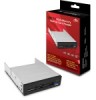
Connecting Your Front Panel Device SATA andSATA Power Connector SATA Power SATA OOO 20-Pin USB 3.0 or 9-pin USB 2.0 USB 3.0 20-Pln* USB 2.0 2x5 10-Pin* ODD MolexPower (4-PinPeripheral) 5 Make sure all connection are connected well and place the cover back on to your case. 6 Drivers will be automatically detected and installed. Your device • will be ready for use. * Diagram shown is the USB 3.0 20-Pin or USB 2.0 10-Pin found on supported motherboards or expansion cards. Please refer to your motherboard manufacturer's documentation for the location of these ports. ** Please make sure that the connectors are oriented properly before connecting. Incorrect orientation may cause severe damage to your device or electrical shock. 4-Pin Peripheral Molex** 4. Converting Your 3.5"Front Panel Device to 5.25"Form Factor If you would like to mount your 3.5" device into your 5.25" drive bay, you may do so by using Vantec's HDA-525P 3.5" to 5.25" bay converters. Follow the steps below to convert your device form factor to 5.25". O O Prepare the 3.5" to 5.25" front panel converter kit. 2 Slide in the 3.5" front panel device into the front bay converter kit until the front panel is flush. 3 • Secure with the screws provided by the 3.5" to 5.25" front panel converter bracket. L,ArrEC Information in this document is subject to change without notice. Reproduction of these materials in any manner whatsoever without written permission is strictly forbidden. Printed in China aG407 Printed on Recycled Paper. vl.01 wwvv.vantecusa.com Copyright O 2012 Vantec Thermal Technologies. All Right Reserved. I All Registered Trademarks Belong To Their Respective Companies.
-
 1
1 -
 2
2
 |
 |
