ViewSonic VX900 Quick Start Guide - Page 2
Vx9 Lcd Monitor - 2 monitor
 |
UPC - 766907802627
View all ViewSonic VX900 manuals
Add to My Manuals
Save this manual to your list of manuals |
Page 2 highlights
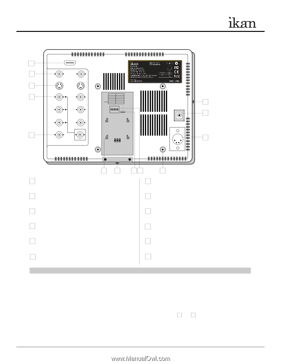
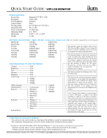
QUICK START GUIDE / VX9 LCD MONITOR MONITOR DIAGRAMS Rear view HDMI 1 2 VIDEO 3 Y/C Switch On 4 1 50p Y 720p 2 3 30p 25p 4 24p 1080p 5 24psf ON OFF Pb 1 2 3 4 5 Pr CAUTION: TURN OFF POWER BEFORE ADJUSTING 5 SDI SWITCHES OUT IN + + 11 6 DC 12V + 7 + DC 12V - 20V 12 11 10 9 8 1 HDMI terminal HDMI input only 7 DC 12V-20V power terminal XLR DC Connection 2 VIDEO terminal (BNC) IN : Composite signal input terminal OUT: : Input signal through-out terminal 3 Y/C terminal IN : SVHS signal input terminal OUT: : Input signal through-out terminal 4 YPbPr terminal (BNC) IN : Component signal input terminal OUT: : Input signal through-out terminal 5 SDI (HD/SD) terminal (BNC) IN : SDI input terminal - 1.5G OUT: : Input signal through-out terminal (Reclock) 6 DC 12V power terminal Standard DC Connection 8 Vesa 100mm Mount Holes Threaded for M4x.07 screws. Use to attach pro battery plate adapter or for mounting third party vesa mounts. 9 DIP Switch Enable special 720p modes. For the monitor to correctly display certain 720p signals, it is necessary to configure the DIP switches. 10 USB terminal For factory service use only 11 ¼-20 Threaded insert (on four sides of monitor) Mounting Monitor 12 DV Battery Plate Slot Mounting ikan DV battery plate **NOTE - The user must turn the monitor off before making changes to the DIP switches. Failure to do so may damage the monitor or make the monitor unusable. DIGITAL TO ANALOG CONVERSION [SDI > YUV] The monitor can convert digital SDI signals to Analog YUV. A signal from the SDI will be displayed on the YPbPr analog outputs. This is a straight digital to analog conversion only. There is no up converting, down converting or standards conversion available in this feature. This feature works in one direction SDI to analog. It will not work in reverse. POWERING THE MONITOR 1. Plug the AC power adapter into the power input jack (See rear view diagram 6 or 7 above). 2. Attach the DV battery plate on the slot, and connect DV battery to the plate. 3. Connect a pro battery using the optional pro battery plate and then plugging that plate with the power tap cable into the DC-In connector. The pro battery plate kits (PBK17-S or PBK17-A) allow you to go into the field using standard V-Mount or Gold-Mount batteries. 3903 Stoney Brook Dr. Houston TX 77063. 1-713-272-8822. [email protected] © 2010 ikan Corporation. All right reserved. www.ikancorp.com
-
 1
1 -
 2
2 -
 3
3
 |
 |