Viking BVGRC8486GWSS Installation Instructions - Page 10
Final Installation, Standoff Spacer Removal, Connecting Gas & Electric, Anti-tip Device
 |
View all Viking BVGRC8486GWSS manuals
Add to My Manuals
Save this manual to your list of manuals |
Page 10 highlights
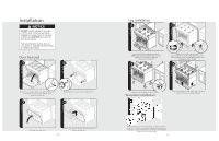
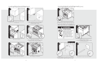
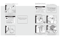
Anti-tip Device Installation (cont.) 4 Attach bracket with mounting hardware provided. Connecting Gas & Electric DANGER GAS LEAK HAZARD To avoid risk of personal injury or death; leak testing of the appliance must be conducted according to the manufacturer's instructions. Before placing appliance in operation, always check for gas leaks with soapy water solution. • DO NOT USE AN OPEN FLAME TO CHECK FOR GAS LEAKS. Note: Refer to electrical and gas requirements section for proper installation information. 1 Connect gas and electrical. Before placing appliance in operation, always check for gas leaks. This must be performed by your dealer, a qualified licensed plumber, or gas service company. 18 Standoff Spacer Removal Note: Standoff spacers can only be removed if range is installed against a NON-COMBUSTIBLE wall. DANGER FIRE HAZARD Backguards come standard with standoff spacers which provide a barrier between back of range and rear wall. These must be in place for adequate ventilation. The standoff spacers may only be removed if range is installed against a non-combustible wall. Note: Standoff spacers can only be removed if range is installed against a NON-COMBUSTIBLE wall. Please see the backguard install guide for instructions on how to remove the standoff spacers. Final Installation 1 2 1 x4 2 Install island trim. 3 Slide range into place. Be sure anit-tip bracket slides into the anit-tip opening. 4 Burner caps are packed in cardboard top pack with the grates. Place burner on top of range. Place burner grate on top of burner cap and grate support. (03.9/58"cm) Check that unit is level side to side and front to back. The side trim must be 3/8" (0.95 cm) above countertop. If unit is not level repeat Steps 5-7 of "Leveling/Adjustments/Alignment" section. 19
-
 1
1 -
2
-
3
-
4
-
 5
5 -
 6
6 -
 7
7 -
 8
8 -
 9
9 -
 10
10 -
 11
11 -
 12
12
 |
 |
