Viking DFB450 Professional Stainless Steel Handle Kit - 23 inch - Installation - Page 2
Dfwd - Warming Drawer, Custom Front Dimensions Using Kit #phk23, Dfud - Dishwasher, Custom Front
 |
View all Viking DFB450 manuals
Add to My Manuals
Save this manual to your list of manuals |
Page 2 highlights
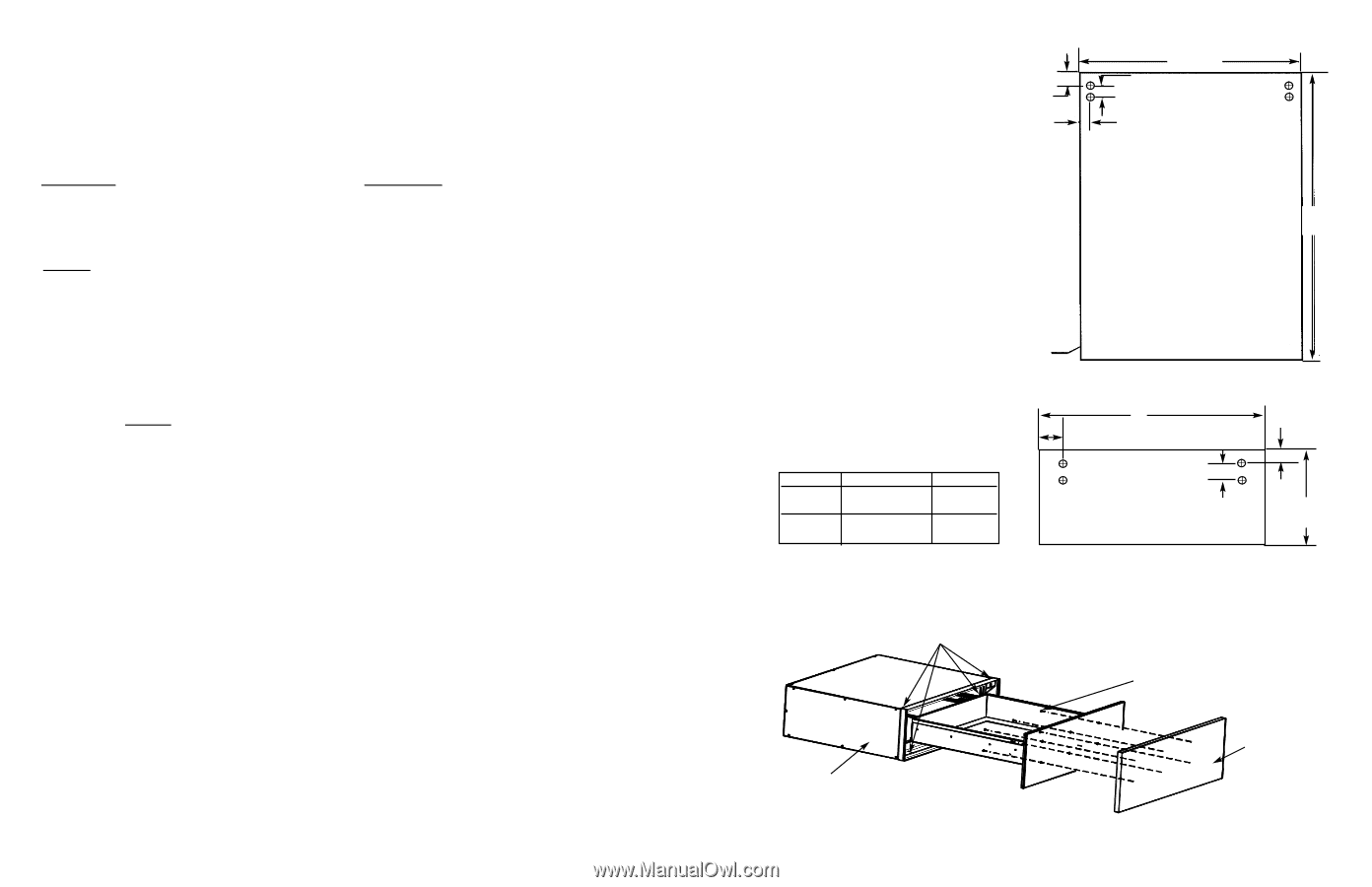
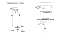
IMPORTANT-PLEASE READ AND FOLLOW •Before beginning, please read these instructions completely and carefully. •Do not remove permanently affixed labels, warnings, or plates from the product. This may void the warranty. •Please refer to the Installation Instructions for more information on installing the custom door fronts. •The installer should leave instructions with the consumer who should retain for local inspector's use and for future reference. CUSTOM FRONT HANDLE INSTALLATION INSTRUCTIONS Parts included: Required Tools: Professional Series Handle Electric Drill Phillips Head Screwdriver (2) End Caps Pilot Bit Masking Tape (4) 1/4" x 1 1/4" Phillips Head Screws 1/4" (.6 cm) Drill Bit Pencil Installation Instructions Counter Sink Drill Bit Tape Measure Rubber Mallet To Install: 1. Place a handle encap on both ends of the handle tube. Tap the endcaps firmly into place with a rubber mallet ensuring that both endcaps mounting surfaces are parallel. 2. Using the illustration provided, layout the handle location on the custom door. It is recommended that masking tape be placed where the four holes will be drilled to help mark the hole placement and to prevent any damage to the door when drilling the holes. 3. Before drilling, check handle against supplied dimensions. Drill small pilot holes completely through the door at each of the four hole locations. 4. The Professional Series handle will be mounted using the screws provided. These screws require the holes to be countersunk on the back of the panel in order for the door to fit flush against the panel. Using the four pilot holes as guides, drill completely through the door in the four hole locations with a 1/4" (.6 cm) bit. Countersink the four holes on the backside of the custom door panel. 5. Align the holes in the endcaps with the holes on the panel and attach the Professional Series handle to the panel using the four screws provided. 2 DFUD - DISHWASHER CUSTOM FRONT DIMENSIONS (Using Kit #PHK23) 1" (2.5 cm) 23 1/2" (59.7 cm) 1 3/8" (3.5 cm) 7/8" 2.2 cm) 29 3/4" (75.6 cm) 3/4" Thick (1.9 cm) DFWD - WARMING DRAWER CUSTOM FRONT DIMENSIONS (Using Kit #PHK23) A B Custom Door Front View 1" (2.5 cm) DFWD170 DFWD100 A 26 1/2" 29 1/2" (67.3 cm) (74.9 cm) B 2 3/8" 3 7/8" (6.0 cm) (8.6 cm) CUSTOM FRONT INSTALLATION 1. Open the drawer and remove the pan. 2. Center the custom front on the inside panel. 3. Attach the custom front with the (6) six #8 x 3/4" screws provided. Mounting Screws (4) - #8 x 3/4" 1 3/8" (3.5 cm) (6) - #8 x 3/4" screws to attach custom front 11" (27.9 cm) Cavity Assy. Custom Front 3
-
 1
1 -
 2
2 -
 3
3 -
 4
4
 |
 |