Viking DFB450 Designer Stainless Steel Handle Kit - 23 inch - Installation Ins - Page 2
IMPORTANT, Handle Installation - dimensions
 |
View all Viking DFB450 manuals
Add to My Manuals
Save this manual to your list of manuals |
Page 2 highlights
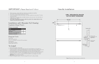
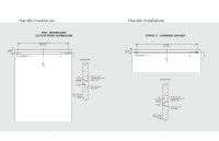
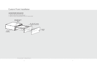
IMPORTANT-Please Read and Follow! • Before beginning, please read these instructions completely and carefully. • Use caution during assembly to minimize scratches. • Do not remove permanently affixed labels, warnings or plates from the product. This may void the warranty. • Please refer to the DFRD, DFB and DFWD Installation Instructions for more information on installing the door panel. • The installer should leave instructions with the customer who should retain for local inspector's use and future reference. Installation with Wooden Full Overlay Custom Door Front Parts Included Part Designer Handles End Caps #10 x 3/4" Hex Head Screws Installation Instructions Quantity (1) (2) (4) Required Tools Electric Drill 3/16" (0.5 cm) Drill Bit 7/16" (1.1 cm) Spade or Forstner Bit (Counterbore) Tape Measure Hex Head Screw Driver Masking Tape and Pencil To Install: 1. Locate the wooden custom panel. 2. Using the illustrations on the next page, layout the handle location on the panels. It is recommended that masking tape be placed where the four holes will be drilled to help mark the hole placement and to prevent any damage to the door when drilling the holes. 3. The Designer handle will be mounted using (4) of the #10 x 3/4" Hex head screws provided. Using the 3/16"(0.5 cm) drill bit, drill completely through the door in the hole locations. Using the 7/16" (1.1 cm) bit, counter-bore four holes 1/2" (1.2 cm) deep max. on the BACKSIDE of the custom door panel. 4. Attach the Designer handle to the panel using (4) #10 x 3/4" screws provided. 2 Handle Installation 1-5/8" (4.1 cm) DFRD - REFRIGERATED DRAWER CUSTOM FRONT DIMENSIONS 20-21/32" (52.5 cm) 13/16" (2.1 cm) CL A A Section A-A 13/16" (2.1 cm) 3/4" (1.9 cm) Full Overlay Panel 7/16" (1.1 cm) Counter Bore x 1/2" Depth (max) 3/16" (0.5 cm) Thru Hole Note: Refrigerated drawers require two handle kits. 3
-
 1
1 -
 2
2 -
 3
3 -
 4
4
 |
 |
