Viking FDWB301R Top Kit - Installation Instructions - Page 2
F20235A EN
 |
View all Viking FDWB301R manuals
Add to My Manuals
Save this manual to your list of manuals |
Page 2 highlights
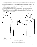
7. Using the panel hole locations as a template, drill ten (10) holes on the cabinet rear with a 9/64" (.36 cm) diameter drill bit. (figure 3) 8. Attach the panel to the rear of the unit using the ten (10) black #8 sheet metal screws provided. 9. Plug unit into the receptacle and roll the unit so that the rear of the unit makes contact with the wall in the final location. 10. Adjust to desired height, and level unit by turning the front and rear leveling wheel bolts clockwise to raise the unit and counterclockwise to lower the unit. Rotate leveling feet until firmly in place against the floor. The unit back should be tightly located against the back wall. 11. Using the top panel rear flange as an attachment device, locate holes in the flange that are aligned with a minimum of two wall studs. (figure 4) 12. Using wood screws that are a minimum of 1½" long, attach the top panel flange to the anchoring device (wall studs or other mechanical device). Ensure that the screw heads will not pull through slots in top panel. Use washer if necessary to prevent pull through. Studs Screws Wall Panel hole locations Figure 4 Figure 3 (Rear of unit) VIKING RANGE CORPORATION 111 Front Street • Greenwood, Mississippi 38930 USA • (662) 455-1200 Specifications subject to change without notice For more product information, call 1-888-VIKING1 (845-4641), or visit our web site at www.vikingrange.com F20235A EN (030211)
-
 1
1 -
 2
2
 |
 |
