Viking MVWD630SS Installation Instructions - Page 4
Specifications, Cutout Dimensions
 |
View all Viking MVWD630SS manuals
Add to My Manuals
Save this manual to your list of manuals |
Page 4 highlights
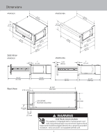
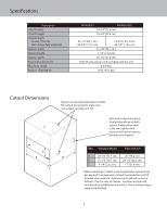
Specifications Description Overall width Overall height Overall depth To end of handle With drawer fully extended Interior width Interior height Interior depth Electrical requirement Max Amp Usage Approx. shipping wt. MVWD630 MVWD630BG 29-3/4" (75.6 cm) 10-3/4" (27.3 cm) 25-1/4" (64.1 cm) 44-3/4" (113.7 cm) 24-3/16" (61.4 cm) 44-1/3" (112.5 cm) 22-1/8" (56.1 cm) 5-1/2" (14.0 cm) 20-1/4" (51.4 cm) 120V/15 amp power cord included with the unit 4.0 Amps 90 lb. (40.5 kg.) Cutout Dimensions Spacers can be placed anywhere inside the cutout as needed to make sure unit is level and does not tilt. Electrical receptacle can be located any where on back cutout. Preferred location is the rear right so that excess cord can lie in space behind control panel. C A B DIM Standard Mount Flush Mount* A 28-1/4" (71.7 cm) 30" (76.2 cm) B 23-1/2" (59.7 cm) 24-1/2" (62.2 cm) C 9-1/4" (23.5 cm) 11" (27.9 cm) *When installing in a flush mount application, spacers may be required to ensure unit remains level and does not tilt forward when opened. Spacers can be placed on top or bottom - front or rear of cabinet. Location and size will vary based on installation and cutout. Outer cabinet edges need to be finished. 4
-
 1
1 -
 2
2 -
 3
3 -
 4
4 -
 5
5 -
 6
6 -
 7
7 -
 8
8
 |
 |
