Viking RVGR3302 LP/Propane Conversion Kit - RLPKR2 - Installation / Use and Ca - Page 3
RNKR2 NAT Conversion Kit Instructions for RVGR3302/RVDR3302 Ranges
 |
View all Viking RVGR3302 manuals
Add to My Manuals
Save this manual to your list of manuals |
Page 3 highlights
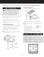
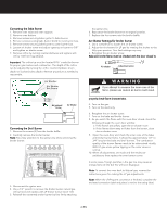
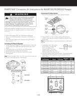
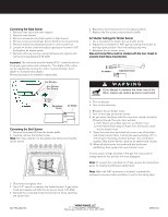
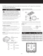
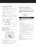
RNKR2 NAT Conversion Kit Instructions for RVGR3302/RVDR3302 Ranges WARNING The conversion must be performed by a qualified installer or gas supplier in accordance with the manufacturer's instructions and all codes and requirements of the authority having jurisdiction. Failure to follow ALL instructions could result in serious injury or property damage. The qualified agency performing this work assumes responsibility for this conversion. The pressure regulator and the burner orifices are set for LP gas. To use natural gas, the regulator and burner orifices must be converted. To convert the range to NAT gas, follow these instructions: 1. Disconnect all electrical power at the main circuit breaker or fuse box. 2. Shut off the gas supply to the range by closing the manual shut-off valve. Converting the Pressure Regulator 1. Locate the pressure regulator which can be found on the back of the range on the right hand side if facing the back of the range. 2. Unscrew the hex nut cap from the top of the regulator. 3. Unsnap the plastic plunger from the hex nut. 4. Reverse the plunger and reinstall onto the hex nut by pressing firmly. Note: Plunger is marked "Nat" and "LP". Converted fuel type will be shown on the lower portion of the plunger. NAT LP Apply sideways finger pressure to remove pin from cap. conversion LP N AT conversion LP N AT Converting the Surface Burners 1. Remove the top grates, burner caps, and burner heads. Burner grate Burner cap Burner head Burner base Orifice spud 2. Using a 9/32" or 7 mm nut driver remove the top burner orifices. These may be accessed through the opening in the burner base. Note: Save these orifices for future conversion back to NAT gas, if required. 3. Locate the proper NAT surface burner orifices included with 0.79 the kit according to the diagram below. The orifice Orifice Orifice stamp stamp can be either the metric diameter size or the orfice drill size. 4. Install the orifices in their correct location. To prevent leakage, make sure the orifice spuds are securely screwed into the burner base. Part Number 057747-901 057747-902 057747-903 057747-905 057747-904 015695-000 PB040034 Burner Left front (A) Left rear (B) BTU Rate Diameter mm 18,000 2.00 9,100 1.38 Center (C) 9,100 1.38 Right rear (D) 12,000 1.58 Right front (E) 17,000 1.88 Bake 30,000 2.58 Broil 15,000 1.87 Orifice Stamp 200 138 138 158 189 #38 #50 B C D 3-EN A E
-
 1
1 -
 2
2 -
 3
3 -
 4
4 -
 5
5 -
 6
6 -
 7
7 -
 8
8
 |
 |
