Viking VCBB5363E Installation Instructions
Viking VCBB5363E Manual
 |
View all Viking VCBB5363E manuals
Add to My Manuals
Save this manual to your list of manuals |
Viking VCBB5363E manual content summary:
- Viking VCBB5363E | Installation Instructions - Page 1
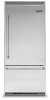
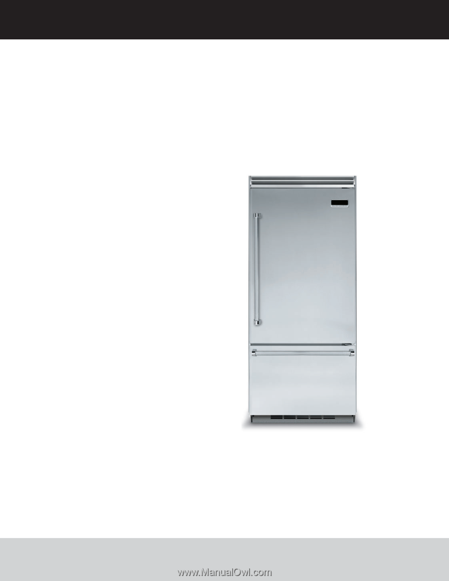
Installation GUIDE 5 SERIES Professional Built-In Bottom-Freezer Refrigerator VCBB5363E / CVCBB5363E - Viking VCBB5363E | Installation Instructions - Page 2
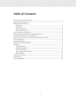
17 Hinge Adjustment 18 Kickplate Installation 21 Door Stop Adjustment 21 System Specifications and Data 22 Final Installation 23 Performance Checklist 24 Control Panels 25 Service & Registration 26 2 - Viking VCBB5363E | Installation Instructions - Page 3
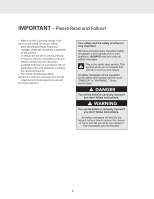
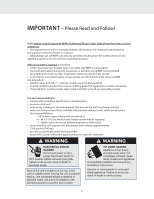
including fire-rated construction. • The installer should leave these instructions with the consumer who should retain them for local inspector's is very important. We have provided many important safety messages in this manual and on your appliance. ALWAYS read and obey all safety messages. This - Viking VCBB5363E | Installation Instructions - Page 4
water or moisture. • Viking Range, LLC will NOT warranty any problems resulting from GFI outlets prevent the unit from being serviced. • make sure that you valve) • assure that floor will support unit, door panels and contents ( installed and secured per installation instructions. Use two or more - Viking VCBB5363E | Installation Instructions - Page 5
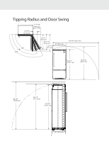
Tipping Radius and Door Swing 12-5/16" (31.0 cm) 17-11/16" (44.9 cm) 90º 110º 120º 30 1/4" (76.8 cm) 32 11/16" (83.0 cm) 34 7/16" (87.5 cm) 36" (94.4 cm) 118 7/8" (302.0 cm) 82 3/4" (210.1 cm) 90 3/16" (229.1 cm) 86 1/8" (218.8 cm) 85 1/2" (217.2 cm) 82 3/4" (210.1 cm) 24" (61.0 cm) 5 - Viking VCBB5363E | Installation Instructions - Page 6
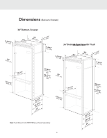
Dimensions (Bottom-Freezer) 36" Bottom-Freezer 3-(91.19/c3m2) " (913.56"cm) (883.95"cm) (13-.81c/m2") 9(2-35.3/3c2m") (1352.21"cm) 2(667-.31/c2m") 2(358-.15/c1m6)" (8212m0-.3i2n/.c4m") (8241m-31t.a5o/x1c.6m") 22((525026--..3743//cc14mm6"))" (612.04"cm) Note: Flush Mount Trim (PBIRFTKSS) - Viking VCBB5363E | Installation Instructions - Page 7
Specifications (Bottom-Freezer) Description Overall width Overall height (from bottom) Overall depth from rear Cutout width Cutout height Cutout depth Electrical requirements Maximum amp usage Inlet water requirements Overall interior dimensions Refrigerator Freezer Total capacity Approximate - Viking VCBB5363E | Installation Instructions - Page 8
Cutout Dimensions (Bottom-Freezer) (612.04"cm) 36" Bottom-Freezer See Anti-Tip board installation (22.99"cm) Electric Outlet Location (15.62"cm) (22.99"cm) (ao2np1t8e0i-nt.25iipn-cg7bm/oh8)aemr"igdihn&t. (a2on1p8t3ei-4.nt5i-ipn1cgbm/oh1)ae6mrigd"ah&xt. PFlush M(9o1.u5n3ct(96mo0")n.8lyc3m5(-) - Viking VCBB5363E | Installation Instructions - Page 9
Anti-Tip Dimensions (Bottom-Freezer) 36" Bottom-Freezer Anti-Tip Location (2at0on71tbi.9-6ot-itpc3tmob/m8)oma"orfdin. (2at0on48tb.i06-ot-itcp1tmob/m)2oma"orafdx. Two 2"x 4" Mounting Boards 3" (7.6 cm) x 3-1/2" (8.9 cm) (7.63"cm) 3(8-.91/c2m") 2(794-.91/c2m") NOTE: If unit is installed deeper - Viking VCBB5363E | Installation Instructions - Page 10
Cabinet Information (Professional) Professional models fit "semi-flush" in standard 24" (61.0 cm) deep cabinet openings. The door face protrudes 1-3/4" (4.4 cm) from the cabinet face. The handle protrudes an additional 2-1/2" (6.4 cm) into the room. Wall 24" (61.0 cm) Standard Cabinet Depth 1-13 - Viking VCBB5363E | Installation Instructions - Page 11
Cabinet Information (Professional with Flush Mount Trim) Professional models with flush mount trim fit flush in standard 24" (61.0 cm) deep cabinet openings with no protrusion into the room except the handle protrudes 2-1/2" (6.4 cm) into the room. Top View Wall 1" (2.5 cm) space if 25" (63.5 cm - Viking VCBB5363E | Installation Instructions - Page 12
Custom Side Panel Dimensions (Professional) 2(527-7.0/1cm6") (15.62"cm) 3/16" (0.5 cm) Back filler panel 3/4" (1.9 cm) End panel 5/32" (0.4 cm) 2(527-7.0/1cm6") (2(2113808.45.25-c-1tc7mo/m/1)8)6m"m"aixn..* (2621-.01/c4m") (15.62"cm) (2(2113808.45.25-c1-tc7mo/m/1)8)6m"m"aixn..* Optional - Viking VCBB5363E | Installation Instructions - Page 13
Custom Side Panel Dimensions (Professional with Flush Mount Trim) (2515-.23/c4m") Z-Bracket 1" (2.5 cm) 1/4" 3/4" (0.6 cm) (1.9 cm) End panel (2(2113808.45.25-c-1tc7mo/m/1)8)6m"m"aixn..* (612.04"cm) (2515-.23/c4m") (2(2113808.45.25-c-1tc7mo/m/1)8)6m"m"aixn..* Optional kickplate Notch, - Viking VCBB5363E | Installation Instructions - Page 14
pounds [540 kg] per unit). • Floors underneath refrigerator are level with surrounding finished floor. • Rear wall is solid and is able to support two horizontally mounted 2 x 4s (included) bolted to two wall studs. The 2 x 4 board bolt heads must be flush with 2 x 4 to prevent obstruction. • Remove - Viking VCBB5363E | Installation Instructions - Page 15
additional length to facilitate moving the unit out of enclosure for cleaning or service. Tubing should be soft instead of rigid and ends should be free of NOT install shut-off valve behind the unit. • The installation of Viking units with a reverse osmosis system is acceptable as long as the water - Viking VCBB5363E | Installation Instructions - Page 16
is in operating position. • All four leveling legs must contact the floor to support and stabilize the full weight. • DO NOT drop unit. • Remove exterior two or more people to move and install unit. Failure to follow this instruction can result in back or other injury. • To avoid personal injury, - Viking VCBB5363E | Installation Instructions - Page 17
Flush Mount Side Trim Installation (Sold Separately) Note: If the unit is to be installed flush with the cabinets, the flush mount side trim must be installed first. If not, skip to "Installation". Step 1 - Locate the necessary parts: Two (2) flush mount trim pieces and a hardware kit with twenty- - Viking VCBB5363E | Installation Instructions - Page 18
Hinge Adjustment 5 2 1 Remove four side screws and remove unit top. 7 1 2 Replace unit top. Replace four side screws. 8b 6 Front of unit 2 1 3 Loosen the four hinge screws. Adjust door. Retighten four hinge screws. 8a Wall 2 x 4 Refrigerator Attach one 2 x 4 to wall stud (refer to dimensions - Viking VCBB5363E | Installation Instructions - Page 19
Hinge Adjustment (cont.) 10a 10b 3" Place unit within 3" (7.6 cm) of being flush with cabinets. Note: To avoid cabinet damage, place cardboard between cabinets and unit. When moving unit, DO NOT crimp, kink or crush water supply line. Carefully move unit until semi flush with cabinet (depending - Viking VCBB5363E | Installation Instructions - Page 20
Hinge Adjustment (cont.) 15 16 Lift unit off rollers to desired height and level unit using a 5/16" head wrench. NOTE: DO NOT use an electric device. Overtightening can cause damage. 17 Screw Wall 2 x 4 Refrigerator Attach unit to wood block using a 22" (55.9 cm) extension and (2) #8x3" wood - Viking VCBB5363E | Installation Instructions - Page 21
Kickplate Installation 18 1 19 1 2 2 Align holes on both ends of louvered panels and insert screws. 3 Using a Phillips screwdriver, attach the kickplate to the unit and adjust to desired height. Door Stop Adjustment (Bottom-Freezer) 20 21 120˚ 110˚ 90˚ 1 3 2 1 2 Open refrigerator door - Viking VCBB5363E | Installation Instructions - Page 22
performance may vary. Must be installed and operated in accordance with manufacturer's recommended procedures and guidelines. Installation instructions, parts and service availability, and standard warranty are included with the product when shipped. This drinking water system must be maintained - Viking VCBB5363E | Installation Instructions - Page 23
Final Installation 22 23 Replace top air grille. 24 Using an 8" (20.3 cm) magnetic nut driver, replace the two 1/4" (0.6 cm) screws. 25 Replace the center grille louver. 26 Open door. The display should flash. Press "ACTIVATE CONTROLS" pad and close door. Note: There is a 6 minute delay - Viking VCBB5363E | Installation Instructions - Page 24
Performance Checklist -Verify cabinet size. -Verify electrical supply and water supply (if applicable). -Install anti-tip device(s) and verify unit is secure. -Position unit in cutout, level at desired height and secure unit. -Plug-in unit and verify operation. -Connect water supply (if applicable - Viking VCBB5363E | Installation Instructions - Page 25
Verify Operations Control Panels Bottom Freezer ACTIVATE CONTROLS FRZ TEMP REF TEMP HIGHER LOWER FREEZER MAX FRZ MAX REF FAST COOL SAB SHOW C F REFRIGERATOR DOOR OPEN POWER HIGH TEMP FAST COOL MAX REF MAX FRZ ALARM OFF DISPLAY OFF 1. Press "ACTIVATE CONTROLS" pad. 2. Verify unit is not - Viking VCBB5363E | Installation Instructions - Page 26
authorized service agency, or if you continue to have service problems, contact Viking Range, LLC at 1-888-(8454641), or write to: VIKING RANGE, LLC PREFERRED SERVICE 111 indicated below. You will need it if service is ever required. Model number Serial number Date of purchase Date installed - Viking VCBB5363E | Installation Instructions - Page 27
27 - Viking VCBB5363E | Installation Instructions - Page 28
F21417D EN Viking Range, LLC 111 Front Street Greenwood, Mississippi 38930 USA (662) 455-1200 For product information, call 1-888-(845-4641) or visit our web site at vikingrange.com UL C UL (101519)
-
 1
1 -
 2
2 -
 3
3 -
 4
4 -
 5
5 -
 6
6 -
 7
7 -
8
-
9
-
10
-
11
-
12
-
13
-
14
-
15
-
16
-
17
-
18
-
19
-
20
-
21
-
22
-
23
-
24
-
25
-
26
-
27
-
28
 |
 |
Installation
GUIDE
5 SERIES
Professional Built-In Bottom-Freezer Refrigerator
VCBB5363E / CVCBB5363E