Viking VDSC530 Installation Instructions - Page 12
Leveling/Adjustments/Alignments, Connecting Gas & Electric, Anti-tip Device Installation
 |
View all Viking VDSC530 manuals
Add to My Manuals
Save this manual to your list of manuals |
Page 12 highlights
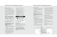
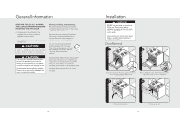
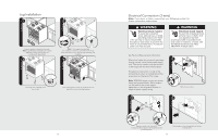
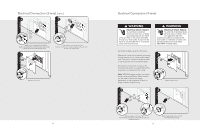
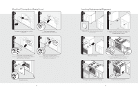
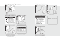
Leveling/Adjustments/Alignments (cont.) 7 Set the high corner of range so that the top of side trim is 3/8" (0.95 cm) above countertop. Level range to high corner. Anti-tip Device Installation WARNING Tipping hazard. To reduce the risk of property damage or personal injury; install anti-tipping device provided in accordance with the installation instructions in this document. Device must be engaged properly to prevent product from tipping over. 2 Y X Me+a1s/u2r"e(m1.e3nctm()A) 1 Measurement (A) Measure from floor to bottom of the anti-tip opening located on the back of range. This will be measurement (A). Range "X" Width Dimension "Y" Dimension 30" 3-5/8" (9.2 cm) N/A 36" 8" (20.3 cm) N/A 48" 5" (12.7 cm) N/A 60" 5" (12.7 cm) 24-7/8" (63.2 cm) Locate anti-tip bracket on rear wall with the top left corner at measurement (A) plus 1/2" (1.3 cm) from the floor and "X" dimension (see chart) from where the right side of range (facing range) is to be located and "Y" dimension (see chart) from where the left side of the range (facing range) is to be located. 22 Anti-tip location for each range width. Anti-tip Device Installation (cont.) 3 4 Mark and drill holes where bracket will be located. Connecting Gas & Electric DANGER Gas leak hazard. To avoid risk of personal injury or death; leak testing of the appliance must be conducted according to the manufacturer's instructions. Before placing appliance in operation, always check for gas leaks with soapy water solution. • DO NOT USE AN OPEN FLAME TO CHECK FOR GAS LEAKS. Attach bracket with mounting hardware provided. Note: Refer to electrical and gas requirements section for proper installation information. 1 Connect gas and electrical. Before placing appliance in operation, always check for gas leaks. This must be performed by your dealer, a qualified licensed plumber, or gas service company. 23
-
 1
1 -
2
-
3
-
4
-
5
-
6
-
 7
7 -
 8
8 -
 9
9 -
 10
10 -
 11
11 -
 12
12 -
 13
13 -
 14
14
 |
 |
