Viking VGIB242TNSS Use and Care Manual - Page 5
Built-in Clearance Dimensions, Performance Checklist, Installation Procedures For Built-in
 |
View all Viking VGIB242TNSS manuals
Add to My Manuals
Save this manual to your list of manuals |
Page 5 highlights
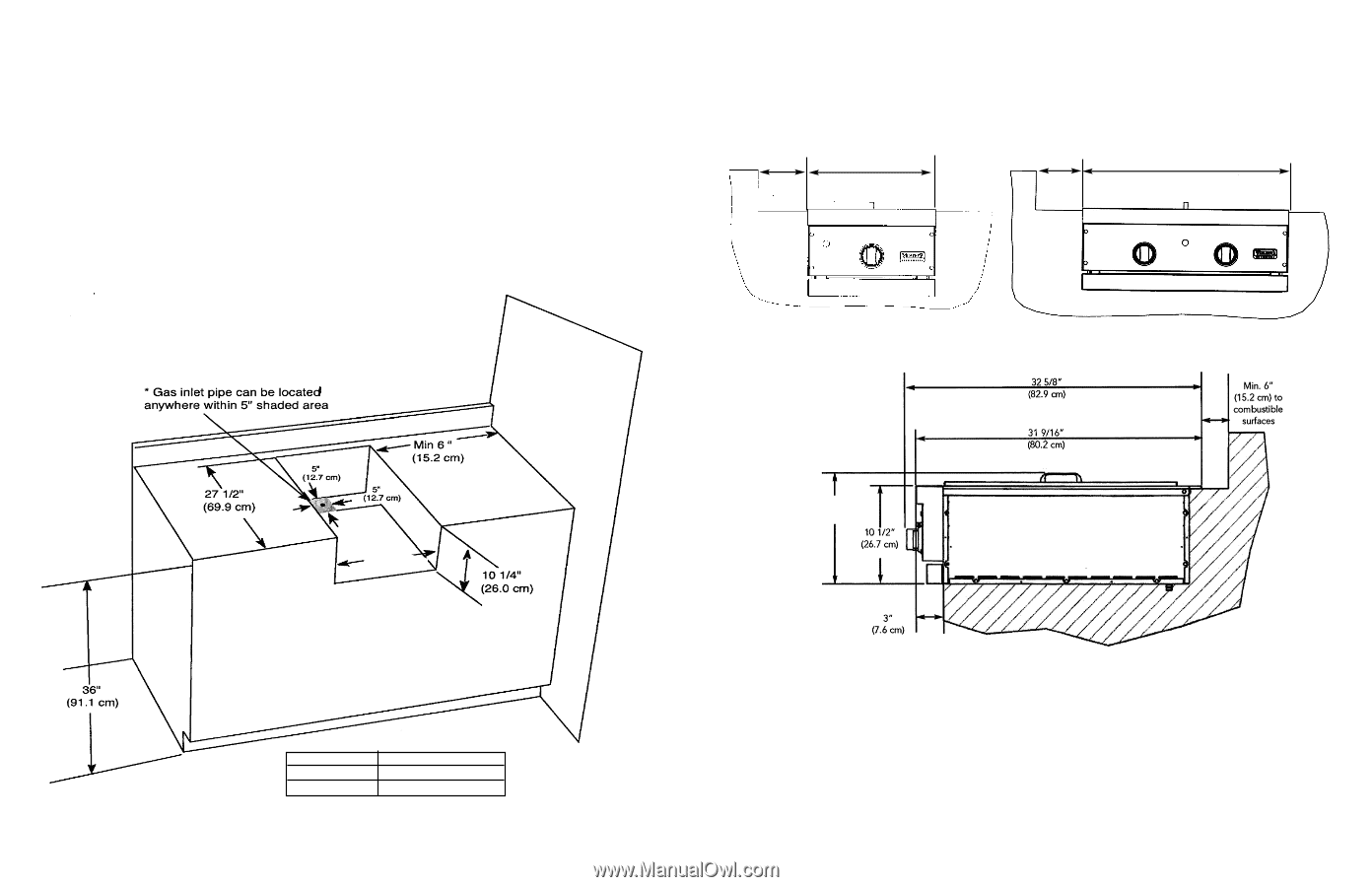
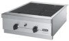
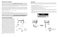
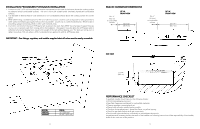
INSTALLATION PROCEDURES FOR BUILT-IN INSTALLATION 1. A minimum of 6" (15.2 cm) from the sides must be maintained from the side of the burner above the cooking surface to adjacent vertical combustible surfaces. The unit is not to be located under overhead unprotected combustible surfaces. 2. It is desirable to allow at least 6" side clearance to non-combustible surfaces above the cooking surface for counter space. 3. When determining a suitable location for the unit, take into account concerns such as exposure to wind, proximity to traffic paths and keeping gas supply lines as short as possible. Locate only in a well-ventilated area. Never locate in a building, garage, breezeway, shed or other such enclosed areas. 4. In a built-in construction where an LP/Propane tank is going to be used, there MUST be some type of support (braces, cut-out, etc.) to prevent tank from moving within the installation. The support must also allow the LP/Propane tank to withstand a horizontal tipping force equal to the weight of the tank without tipping over. The tank can not tip over or deflect more than 1.00 inch when a 38 lb. horizontal force is applied to a 20 lb. LP/Propane tank. IMPORTANT: Gas fittings, regulator, and installer supplied shut-off valve must be easily accessible. BUILT-IN CLEARANCE DIMENSIONS Min. 6" (15.2 cm) to combustible surfaces 15" W. FRONT VIEW 15 5/16" (38.9 cm) Min. 6" (15.2 cm) to combustible surfaces 24" W. FRONT VIEW 26 1/4"" (66.7 cm) SIDE VIEW A MODEL VGIB151T VGIB242T 8 DIM A. 14" (35.6 cm) 24 3/4" (62.9 cm) 11 3/8" (28.9 cm) PERFORMANCE CHECKLIST A qualified installer should carry out the following checks: • All internal packaging removed. • Specified clearances maintained to combustible materials. • Pressure regulator connected and set. • Manual shut-off valve installed and accessible. • Check air shutter adjustment - sharp blue flame, no yellow tipping. • Check for gas leaks (odors) at all gas connections. • Each burner lights satisfactory, individually or with adjacent burners lit. Any adjustments necessary that are the result of the installer not following instructions will be responsibility of the installer, dealer or the end user of the product. 9
-
 1
1 -
 2
2 -
 3
3 -
 4
4 -
 5
5 -
 6
6 -
 7
7 -
 8
8
 |
 |