Viking VGSC530 Countertop Rear Trim - Installation Instructions - Page 2
Rear Trim Accessories - vdsc530
 |
View all Viking VGSC530 manuals
Add to My Manuals
Save this manual to your list of manuals |
Page 2 highlights
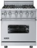
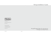
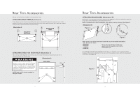
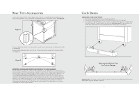
Rear Trim Accessories All rear trim devices are installed in the same basic way. ATTACHING REAR TRIM (Illustration I) Grasp the trim on each end and carefully place in the channels (B) located at each rear corner of the product. Align the screw holes (A) at each end of the trim device with the holes (A) in each rear channel of the product. Secure with the 4 enclosed screws. (Illustration I) B RANGETOP REAR VIEW B RANGE REAR B VIEW B A A ATTACHING SHELF ON HIGH-SHELF (Illustration II) Place the top rolled edge (X) over the front lip of the high-shelf back trim and secure with the 4 enclosed screws, two at each end. WARNING (Illustration II) To reduce the risk of fire or injury to HIGH SHELF persons, check to make sure all packaging X has been removed from the outside and inside parts of the rear trim device before installing. MAKE SURE ALL CORRUGATED MATERIAL IS REMOVED FROM INSIDE THE HIGH SHELF. NOTE: High shelf is already installed on Designer models. A 2 Rear Trim Accessories ATTACHING BACKGUARD (Illustration III) Backguards come equipped with Nylon Spacers (See Figure 1), which are needed to space the range off a combustible wall a prescribed safe distance. Note: If the back wall is Non-Combustible, these spacers can be removed. (See Figure 2) (Illustration III) Figure 1 Figure 2 These spacers can also be removed if used with any of the models listed below: • 30", 36" and 48" VGCC • VDSC530 • VDSC536 • VGRT530 • VGRT536 *If you have one of these models, the spacers are not required, even if with a combustible wall. On VGSC530, VGSC536 and VGSC548 models there is a regulator cover supplied with the backguard that must be attached to the oven, with the supplied screws, before the backguard is attached. (See Figure 3) Figure 3 3
-
 1
1 -
 2
2 -
 3
3 -
 4
4
 |
 |