Viking VISC530 Installation Instructions - Page 11
Final Installation, Anti-tip Device Installation
 |
View all Viking VISC530 manuals
Add to My Manuals
Save this manual to your list of manuals |
Page 11 highlights
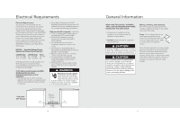
Anti-tip Device Installation (cont.) 4 1 2 Attach bracket with mounting hardware provided. Final Installation 1 Note: Refer to range electrical requirements section for proper installation information. Connect electrical in shaded area. See the "Electrical Requirements" section for more information. 2 3 FRONT REAHR OT FRONT REAHR OT Install island trim. Attach with four screws provided. 20 Slide range into place. Be sure anti-tip bracket slides into the anti-tip opening. 4 (03.9/58"cm) Check that unit is level side to side and front to back. The side trim must be 3/8" (0.95 cm) above countertop. If unit is not level repeat steps 5-7 of "Leveling/Adjustments/Alignment" section. 21
-
 1
1 -
2
-
3
-
4
-
5
-
 6
6 -
 7
7 -
 8
8 -
 9
9 -
 10
10 -
 11
11 -
 12
12 -
 13
13 -
 14
14
 |
 |

21
3/8”
3/8”
(0.95 cm)
(0.95 cm)
3/8”
(0.95 cm)
4
Check that unit is level side to side
and front to back. The side trim must be 3/8” (0.95 cm)
above countertop. If unit is not level repeat steps 5-7
of “Leveling/Adjustments/Alignment” section.
20
1
Note:
Refer to range electrical
requirements section for proper
installation information.
1
2
4
Attach bracket with
mounting hardware provided.
Connect electrical in shaded area. See the “Electrical
Requirements” section for more information.
Final Installation
Anti-tip Device Installation
(cont.)
2
Install island trim. Attach with four screws provided.
3
Slide range into place. Be sure anti-tip
bracket slides into the anti-tip opening.