Viking VMOC206SS Flush-mount Kit for VMOC Microwave with 27 inch Trim Kit- PMF - Page 1
Viking VMOC206SS Manual
 |
View all Viking VMOC206SS manuals
Add to My Manuals
Save this manual to your list of manuals |
Page 1 highlights
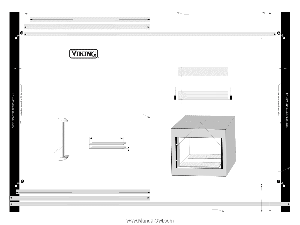
5/16" (8.77 mm) =" Centerline to hole 12-13/16" (324.63 mm) =" Centerline to cutout 13-7/16" (341.6 mm) =" Cutout Opening Width 26-15/16" (683.2 mm) BUILT-IN TRIM KIT FLUSH MOUNTING TEMPLATE FOR CUSTOM SERIES MICROWAVE OVEN 1. Align the Flush Mounting Template center line with the center of the cabinet. Align the Floor Line with the bottom of the cabinet at the desired height. Tape it in place. 2. Cut the cabinet opening along the three Cabinet Cutout Lines and the Floor Line. 3. Install two Side Spacers (see FIGURE 1) and two Bottom Spacers (see FIGURE 2) as specified in FIGURE 4. 4. Cut out the Side Spacer Templates (R and L) and align the indicated edge to the corresponding Side Spacer (see FIGURE 3). Be careful to align the Floor Line to the bottom edges of the Side Spacers. 5. Predrill two holes indicated "A" in Side Spacer - R with a / " drill bit. 6. Predrill two holes indicated "B" in Side Spacer - L with a / " drill bit. 7. Remove template from the cabinet. CENTER LINE (2) bottom spacers 24-5/8" width 1" (25.4 mm) FIGURE 1 Side Spacer (2 required) Must protrude from edge of cabinet cutout towards center as shown. FIGURE 2 Bottom Spacers (2 required). 1-5/8" height TINSKB145MRR0 UB4 @" Centerline to hole 14-5/16" (362.73 mm) @" Centerline to cutout 14-15/16" (379.71 mm) @" Cutout Opening Width 29-15/16" (759.42 mm) CABINET CUTOUT LINE The exhaust duct should be aligned with the front of the bottom spacer closest to the cabinet opening. The exhaust duct should align left to right with the left and right edges of the bottom spacers. The exhaust duct should be secured to the bottom spacer with Screw (C). 24-5/8" (625.5 mm) 4" (2) Bottom Spacer 22-1/16" (561.0 mm) 12-1/8" (308.45 mm) TOP VIEW 4" 1-15/16" (50.35 mm) FIGURE 3 Front of Cabinet (1) Bottom Spacer 1-15/16" (49.9 mm) Edges to align Side Spacer Templates (R and L) Side Spacer L Side Spacer R FIGURE 4 Bottom Spacers centered with cabinet cutout CABINET CUTOUT LINE 2-13/16" (71.1 mm) FLOOR LINE OF CUTOUT OPENING Height Distance Between Holes A 15-3/4" (399.63 mm) Cutout Opening Height 21-5/16" (542 mm) 5/16" (8.77 mm)
-
 1
1
 |
 |