Viking VMOD240SS Installation Instructions - Page 3
Anti-tip Block, Electrical Outlet, Drawer Installation - parts
 |
View all Viking VMOD240SS manuals
Add to My Manuals
Save this manual to your list of manuals |
Page 3 highlights
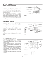
ANTI-TIP BLOCK NORMAL INSTALLATION STEPS ANTI-TIP BLOCK INSTALLATION INSTREUlCecTtIrOicNalSOutlet To reduce the risk of tipping of the dLoracawtieorn, the Anti-Tip block must be properly installed located 14 13/16" above the floor on which the appliance will sit. The 6" Anti-Tip block must be provided by the installer. See FIGURE 1. The Anti-Tip block prevents serious injury that might result from spilled hot liquids. 5" (127 mm) If the DrawerMicro Oven is ever moved to a different location, the Anti-Tip block must also be moved and installed. When installed to the wall, make sure that the 4" FIGURE 3 screws completely penetrate the dry wall and are secured (101.6 mm) in wood or metal so that the block is totally stable. When fastening, be sure that the screws do not penetrate electrical wiring or plumbing. ELECTRICAL OUTLET The electrical requirements are a 120 volt 60 Hz, AC only, 15 amp. or more protected electrical supply. It is recommended that a separate circuit serving only this appliance be provided. The appliance is equipped with a 3-prong grounding plug. It must be plugged into a wall receptacle that is properly installed and grounded. Should you only have a 2-prong outlet, have a qualified electrician install a correct wall receptacle. Note: If you have any questions about the grounding or electrical instructions, consult a qualified electrician or service person. Electrical Outlet Location FIGURE 4 6" (153 mm) Anti-tip Block 5" (127 mm) 4" (101.6 mm) DRAWER INSTALLATION 1. Place the DrawerMicro Oven adjacent to the wall or cabinet opening. Plug the power supply cord into the electrical outlet. 2. Carefully guide the appliance into the prepared opening. Avoid pinching the cord between the oven and the wall. 3. Slide the drawer all the way until the mounting flange is flush with the face of the cabinet. See FIGURE 5A. 4. Open the drawer. Using the 4 holes on the drawer as a template, pre drill the cabinet using a 1/16" bit. See FIGURE 5A. 5. Secure the drawer with the 4 screws supplied. See FIGURE 5B. FIGURE 5A FIGURE 5B E3 Mounting Flange PARTS SUPPLIED 4 Screws
-
 1
1 -
 2
2 -
 3
3 -
 4
4 -
 5
5 -
 6
6 -
 7
7 -
 8
8 -
 9
9 -
10
-
11
-
12
 |
 |
