Viking VUWC1441CRSS Installation Instructions - Page 6
Table B
 |
View all Viking VUWC1441CRSS manuals
Add to My Manuals
Save this manual to your list of manuals |
Page 6 highlights
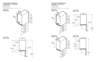
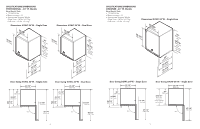
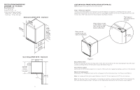
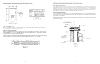
CUSTOM WOOD FRAME INSTALLATION (DFUW Model) (cont.) W H Front of overlay panel 1-23/32" (38.8 cm) Typical 4 Sides Model 15" 24" W 14-5/16" (36.4 cm) 23-7/16" (59.5 cm) H 30-5/16" (76.9 cm) 30-5/16" (76.9 cm) Table A Glass Door Models Figure 2 Glass Door Models Step 5: Clamp panel to door Set the overlay panel on the door front, align the edges, and clamp together. Clamp the panel firmly but be careful not to crush the foam in the door or scratch the door. Step 6: Drill holes in overlay panel Remove the hinge adapter bushings from the top and bottom door hinge adapters. (See Figure 6). Using the holes in the hinge adapters drill 5/16" (8 mm) diameter clearance holes into the overlay panels 3/4" (20 mm) deep. These will be clearance holes for the top and bottom hinge pins. Also, at this time, drill the screw pilot holes for attaching the overlay panel to the door. Select the size of the hole from Table B. Be careful not to drill the pilot holes through the overlay panel but only 1/2" (12.7 mm) deep. Material Type Hardwood Softwood #8 Wood Screw 3/32" (2.4 mm) Diameter. Pilot Hole 5/64" (2.0 mm) Diameter. Pilot Hole Table B CUSTOM WOOD FRAME INSTALLATION (DFUW Model) (cont.) Step 7: Mark and drill lock hole Locate and mark with a pencil the location of the lock hole on the overlay panel, this is the hole in the top corner of the handle side of the door. Remove the clamp and remove the overlay panel from the door. On the backside of the panel where you marked the lock location drill a 13/16" (20.5 mm) diameter counter bore 7/16" (11.0 mm) deep into the overlay panel. Drill a 15/32" (12.0 mm) diameter hole through the overlay panel centered on the counterbore being careful not to splinter the wood on the face side of the panel. (See Figure 3). Step 8: Assemble the lock parts Two (2) lock extensions are supplied with the lock. Use the longer extension for a 3/4" thick overlay panel and the shorter one for a 5/8" thick panel. Assemble the lock extension, cam stop washer, spring washer, and set screw to the lock as shown in Figure 3 and 4. Install this assembly into the overlay panel and secure with the retaining nut using a 15mm socket. Make sure the key slot in the lock is vertical. brass extension spring washer nut cam lock 15/32" hole 13/16" counter bore 7/16" deep 3/4" wood panel Phillips screw Section A-A Scale 1:1 Figure 3 inner door 10 11
-
 1
1 -
 2
2 -
 3
3 -
 4
4 -
 5
5 -
 6
6 -
 7
7 -
 8
8 -
 9
9 -
 10
10 -
 11
11 -
 12
12 -
13
-
14
-
15
-
16
 |
 |
