Vizio VP50 HDTV20A Service Manual - Page 23
Tv_side, Audio, Display, Correctly - capacitors
 |
View all Vizio VP50 HDTV20A manuals
Add to My Manuals
Save this manual to your list of manuals |
Page 23 highlights
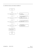
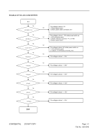
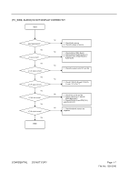
(TV_SIDE, AUDIO) IS NOT DISPLAY CORRECTLY Start Input signal good? Yes J1 input correct? Yes U1.U2 output correct? Yes U7.U8 signal correct? Yes U7.U8 Volt correct? Yes U7.U8 output correct? Yes END N0 1. Check Audio source 2. Check the player of source N0 1. Check signal of Main Board 2. Check signal of Audio Board (J1) 3. Check the wire of Main Board to Audio Board N0 1. Check the output volt of U1 and U2. N0 1. Check C200(Ch R) and C201(Ch L) and C271 (Ch CT) N0 1. Check VCC of U7 and U8. 2. Check 1/2VCC of U7 and U8 (R202.R203.R271). 3. Check ZD2(Ch R) and ZD3(Ch L) and ZD4 (Ch CT) N0 1. Check feedback resistor and capacitor. CONFIDENTIAL - DO NOT COPY Page 9-7 File No. SG-0246
-
 1
1 -
2
-
3
-
4
-
5
-
6
-
7
-
8
-
9
-
10
-
11
-
12
-
13
-
14
-
15
-
16
-
17
-
 18
18 -
 19
19 -
 20
20 -
 21
21 -
 22
22 -
 23
23 -
 24
24 -
 25
25 -
 26
26 -
 27
27 -
 28
28 -
29
-
30
 |
 |

CONFIDENTIAL
–
DO NOT COPY
Page
9-
7
File No. SG-0246
Yes
N0
N0
N0
Yes
Yes
Yes
N0
Yes
N0
N0
Yes
(TV_SIDE,
AUDIO)
IS
NOT
DISPLAY
CORRECTLY
Start
Input signal good?
1. Check Audio source
2. Check the player of source
J1 input correct?
1. Check signal of Main Board
2. Check signal of Audio Board (J1)
3. Check the wire of Main Board to
Audio Board
U7.U8 signal correct?
1. Check the output volt of U1 and U2.
END
U1.U2 output correct?
1. Check C200(Ch R) and C201(Ch
L) and C271 (Ch CT)
U7.U8 Volt correct?
1. Check VCC of U7 and U8.
2. Check 1/2VCC of U7 and U8
(R202.R203.R271).
3. Check ZD2(Ch R) and ZD3(Ch L)
and ZD4 (Ch CT)
U7.U8 output correct?
1. Check feedback resistor and
capacitor.