Vtech 910-915adl User Manual - Page 2
Getting Started, Handset Features, Wall Mounting, Base Unit Features
 |
View all Vtech 910-915adl manuals
Add to My Manuals
Save this manual to your list of manuals |
Page 2 highlights
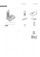
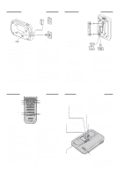
GETTING STARTED WALL MOUNTING AC ELECTRICAL OUTLET TONE TONE PULSE PULSE TELEPHONE WALL JACK Setting Up Your VTECH 910 ADL 1. Choose an area near an electrical outlet and a telephone wall jack. 2. Connect the telephone line cord. Insert one end of the telephone line cord into the jack at the rear of the base unit. Plug the other end into a telephone wall jack. Make sure the plugs snap securely into place. 3. Plug the AC power adapter into an electrical outlet and the DC connector to the back of the base unit. CAUTION:Use only the AC adapter shipped with your 910ADL. This is a Class 2 AC adapter, specifically designed for use with the 910 ADL. NOTE: Connect power to the base unit before placing the handset in the cradle. 4. Set the TONE/PULSE switch on the base unit. If you have touch tone service on your phone line, set the switch to TONE. If you have rotary service, set the switch to PULSE. 5. CHARGE THE HANDSET BATTERIES BEFORE USE. The batteries recharge automatically whenever the handset is in the base unit cradle. The batteries must be charged for 24 hours before using your phone for the first time. 6. CHECK FOR A DIAL TONE. After the batteries are charged, pick up the handset and press the PHONE key. The PHONE indicator should light up, and you should hear a dial tone. If not, see IN CASE OF DIFFICULTY. CAUTION: 1. Never install telephone wiring during a lightning storm. 2. Never install telephone jacks in wet locations unless the jack is specifically designed for wet locations. 3. Never touch uninsulated telephone wires or terminals unless the telephone line has been disconnected at the network interface. 4. Use caution when installing or modifying telephone lines. wsotoudden wallboard 1.Choose a spot near an electrical outlet and a telephone jack.Your phone requires a modular telephone jack and a standard electrical outlet (120v AC). The power cord is six feet long; make sure there is an electrical outlet within reach of the base. The outlet should not be controlled by a wall switch. If the switch is ever turned off, the phone will not operate. 2.Position the wall mount adapter on the base. Line up the tabs on the wall mount adapter with the holes on the bottom of the base. Snap the wall mount adapter firmly in place. 3.Mount the base on the wall. Position the base so the mounting studs will fit into the holes on the bottom of the base. Position the power cord to extend down the wall the phone is to be mounted on. Slide the base down on the mounting studs until it locks into place. 4.Connect the telephone cord. The telephone line cord has a snap-in plug at each end. Insert one of the plugs into the jack on the bottom of the base. Insert the other end of the plug into the wall jack. 5.Connect the power cord. Plug the DC connector into the DC jack at the rear of the base unit. Plug the AC power adapter into an electrical outlet. 6.Set the dial mode switch on the base unit. If you have touch tone service on your phone line, set the switch to TONE. If you have rotary service, set the switch to PULSE. HANDSET FEATURES IN USE LED VOLUME SWITCH PHONE KEY/ FLASH KEY TONE/ KEY PROG KEY IN USE BATT LOW PHONE CHAN OFF 1 2 ABC 3 DEF 4 GHI 5 JKL 6 MNO 7PQRS 8 TUV 9 WXYZ TONE 0OPER # PROG MEM REDIAL BATT LOW LED OFF KEY CHAN KEY MEM KEY REDIAL KEY IN USE LED * The IN USE LED lights when the phone line is being used by the handset. * It flashes in cadence with an incoming ring. * It flashes quickly during PROG mode. BATT LOW LED * The BATT LOW LED will flash when the handset battery is getting low and needs to be recharged. PHONE KEY/ FLASH KEY * Press the PHONE key to make a call. * If you are currently on a call, pressing PHONE flashes the line. This would be used with a feature like call waiting to answer your second call. CHAN KEY * Pressing the CHAN key when the handset is in use will activate a channel change to the next free channel. * This is used if you are experiencing noise or interface on the current channel. OFF KEY * Press the OFF key to exit all modes of operation. MEM KEY * Press the MEM key to enter MEMORY mode. * The sequence for dialing out a speed dial number in memory is: PHONE, MEM, Number Button (0-9). PROG KEY * Press PROG key to enter PROGRAM mode. See Programming Speed Dial Numbers for more details. REDIAL KEY * When you hear the dial tone, pressing the REDIAL key will dial out the last number that was called on your phone. * It can also be used to store the last number dialed into the speed dial memory. See Storing a Redial Number into Speed Dial for details. TONE/* KEY * In PULSE dialing mode, this key is used to switch to Temporary TONE dialing mode. VOLUME SWITCH * Slide switch UP for High Volume (H) setting. * Slide switch DOWN for Low Volume (L) setting. BASE UNIT FEATURES CHARGE LED * The CHARGE LED illuminates steadily when the handset is in the base cradle to indicate that the handset battery is being charged. IN USE LED * Immediately after placing the handset in the base cradle, the IN USE LED flashes to indicate that the initialization (assigning a new security code and channel) is in progress * The IN USE LED will stop flashing and light off when the initialization is complete. * The IN USE LED illuminates whenever the handset is being used. * This LED also flashes with the cadence of the incoming ring. SPARE BATT LED * The SPARE BATT LED illuminates steadily when a battery is placed in the base unit charge cradle. POWER LED * The POWER LED illuminates when the base power adapter is plugged in and power is applied to the base unit. MEMORY DIALING • • • • • SPARE IN CHARGE BATT USEPOWER PAGE TONE/PULSE SWITCH * This switch will switch the phone between TONE dialing and PULSE dialing. PAGE KEY * Press the PAGE key to page the handset. * Press it a second time to cancel a page. * The base will ring the handset 4 times before ending the page automatically. * The handset can also cancel the page by pressing the OFF key.
-
 1
1 -
 2
2 -
 3
3 -
 4
4
 |
 |
