Waring BB300 Instruction Manual - Page 3
Catalog/Model
 |
View all Waring BB300 manuals
Add to My Manuals
Save this manual to your list of manuals |
Page 3 highlights
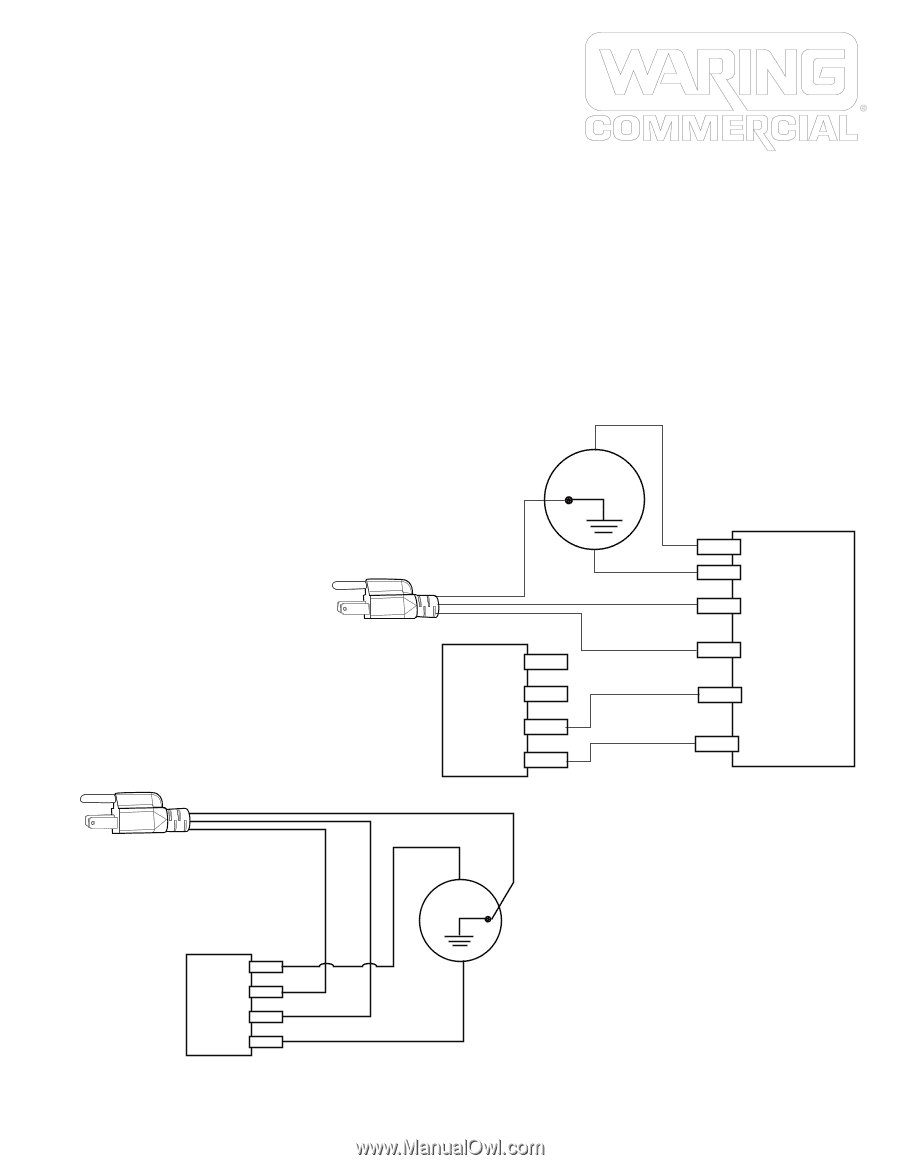
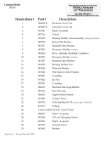
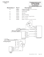
Catalog/Model BB300 Illustration # 30 31 32 33 34 35 36 Part # 503471 503431 033619 013731 033617 035260 033620 033526 Waring Factory Service Center 314 Ella T. Grasso Ave. Torrington, CT 06790 Tele. 1-800-269-6640 Fax 860-496-9017 www.waringcommercialproducts.com Description Cordset Assembly (on units after 2/6/2016) Cordset Assembly Strain Relief Wire Tie Bottom Housing Screw (4 required changed 2/6/2016) Foot (4 required) Screw (2 required on units after 12/3/2015) Green-Yellow Wiring Diagram (units that have the Soft Start PCB) Motor Blue Black White or Blue Black or Brown M- M+ ACN_IN ACL_IN CTL_IN REF_OUT Wiring Diagram Green-Yellow Switch Panel Black Motor Soft Start PCB MN L M Black or Brown White or Blue M+ ACL ACN M- Blue Control Panel Revised March 17, 2016 Page 3 of 3
-
 1
1 -
 2
2 -
 3
3
 |
 |