Waring WDB600 Parts Diagram - Page 2
Illustration, Description
 |
View all Waring WDB600 manuals
Add to My Manuals
Save this manual to your list of manuals |
Page 2 highlights
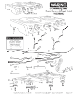
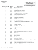
Catalog/Model WDB600 Illustration# 1 2 3 4 5 6 7 8 9 10 11 12 13 14 15 16 17 18 19 20 21 22 23 24 23 24 25 Part# 037470 037471 37472 037473 031118 031117 031115 031116 037474 037475 037476 019123 013731 037477 037478 031104 031103 031112 031129 031108 031109 031120 031106 031107 031112 031111 031110 Waring Factory Service Center 314 Ella T. Grasso Ave. Torrington, CT 06790 Tele. 1-800-269-6640 Description Toggle Switch (2 required) Fax 860-496-9017 www.waringcommercialproducts.com Knob (2 required) 14" Blue Double Lead Assembly 26" Blue Double Lead Assembly Heating Element Spring Washer (4 required) Heating Element Screw (4 required) Ground Lead Nut Ground Lead Spring Washer 12.25" Brown Lead Assembly 27.5" Brown Lead Assembly Green Ready Light with White Lead Assembly (2 required) Crimp Connector (2 required) Wire Ties (5 required) Small Rubber Sleeve (7 required) Large Rubber Sleeve Cord Strain Relief Center Burner Shaft Washer (2 required before bottom plate) Bottom Plate Screw (8 required) Screw (8 required) Plastic Feet (4 required) Rubber Feet (4 required) Screw & Washer Set (4 required comes with screw, 3 washers, 1 spring washer and 1 nut) Center Burner Shaft Washer (2 required after bottom plate) Center Burner Shaft Spring Washer (2 required after bottom plate) Center Burner Shaft Nut (2 required after bottom plate) Page 2 of 3 Revised November 26, 2019
-
 1
1 -
 2
2 -
 3
3
 |
 |