Weider 125 English Manual - Page 7
Tighten the M8 Nylon Locknuts 13 used
 |
View all Weider 125 manuals
Add to My Manuals
Save this manual to your list of manuals |
Page 7 highlights
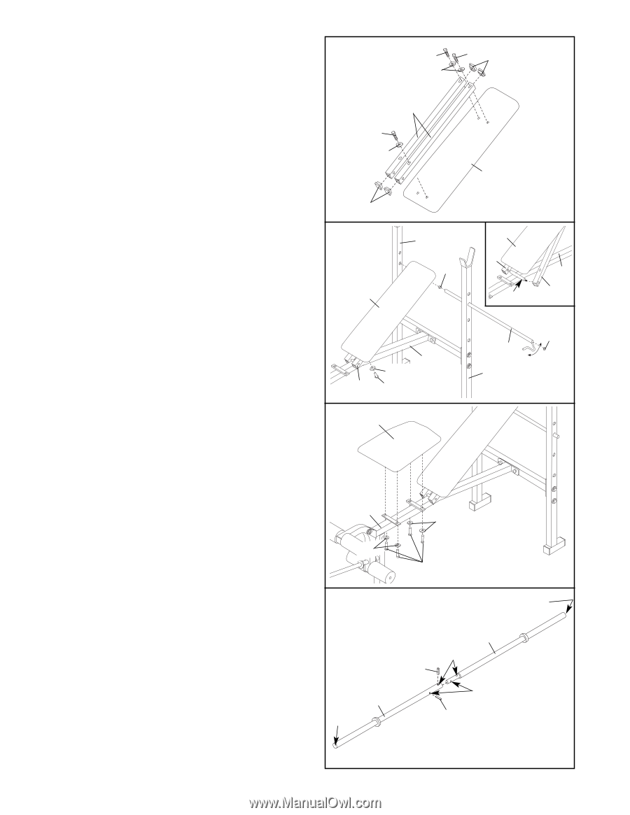
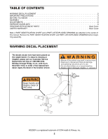
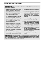
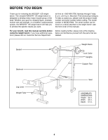
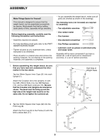
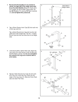
7. Press four 25.4mm Square Inner Cap (25) into 7 the ends of the Backrest Tubes (5). Attach one Backrest Tube (5) to the Backrest (6) with two M6 x 38mm Screws (16) and two M6 Washers (26). Attach the other Backrest Tube to the Backrest with one M6 x 38mm Screw and one M6 Washer. Note: Do not tighten the three Screws yet. A fourth M6 x 38mm Screw will be attached at the end of step 8. 16 16 25 26 5 16 26 6 8. Tap a 19mm Round Inner Cap (9) into each end of the Support Rod (7). Insert the Support Rod through one of the three sets of holes in the Uprights (1). Rotate the Support Rod to the locked position, with the end of the Support Rod clipped onto the Upright. See the inset drawing. Slide the ends of both Backrest Tubes (5) onto the pin on the Frame (2). Attach the free end of the Backrest Tube (5) to the Backrest (6) with an M6 x 38mm Screw (16) and an M6 Washer (26). Fully tighten all four M6 x 38mm Screws. Tighten the M8 Nylon Locknuts (13) used in steps 1 and 3. 9. Attach the Seat (11) to the brackets on the Frame (2) with four M6 x 16mm Screws (15) and four M6 Washers (26). 25 8 6 1 9 2 26 5 16 9 11 6 5 2 Pin 5 9 7 1 2 26 26 15 10. Insert the Inner Bar (29) into the Outer Bar (30) 10 and align the indicated holes. Using a hammer, tap the two Roll Pins (31) into the holes until they are flush with the Outer Bar. Press two 25mm Round Inner Caps (24) into the ends of the Inner and Outer Bars (29, 30). 24 29 Holes 31 11. Make sure that all parts are properly tightened before you use the weight bench. The use of all remaining parts will be explained in ADJUSTMENTS starting on the next page. 30 24 Holes 31 7
-
 1
1 -
 2
2 -
 3
3 -
 4
4 -
 5
5 -
 6
6 -
 7
7 -
 8
8 -
 9
9 -
 10
10 -
 11
11 -
 12
12 -
13
-
14
-
15
-
16
 |
 |