Weider 148 English Manual - Page 9
Lubricate the M10 x 75mm Bolt 46. Attach the Leg
 |
View all Weider 148 manuals
Add to My Manuals
Save this manual to your list of manuals |
Page 9 highlights
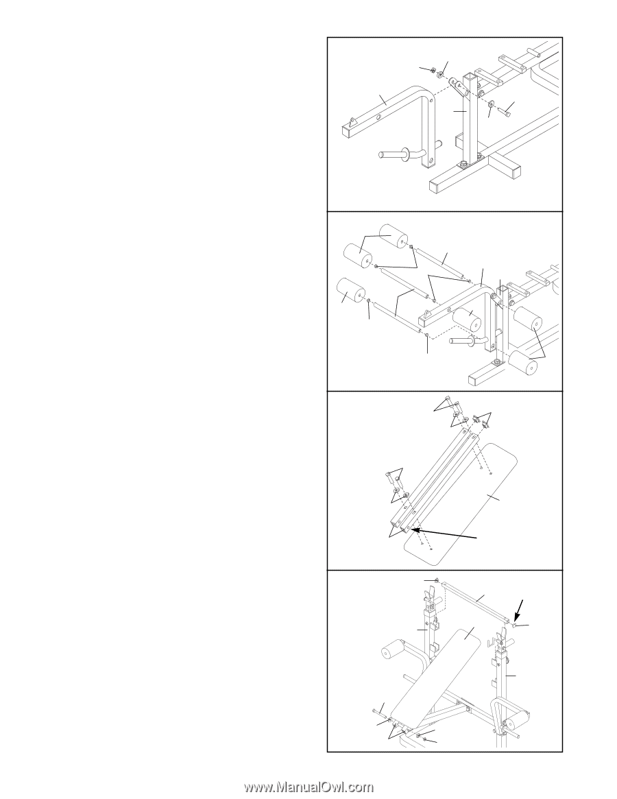
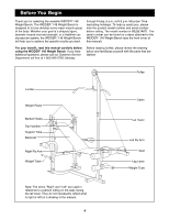
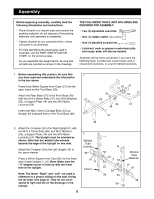
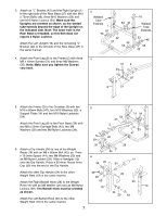
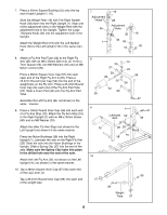
11. Lubricate the M10 x 75mm Bolt (46). Attach the Leg 11 Lever (4) to the Front Leg (8) with the Bolt, two M10 Washers (53) and the M10 Nylon Locknut (54). 53 54 4 46 8 53 12. Press two 25.4mm Round Inner Caps (59) into each Short Pad Tube (10). Press a 25.4mm Round Inner Cap into each end of the Long Pad Tube (41). Insert the Short Pad Tubes into the holes in the Leg Lever (4). Slide two Foam Pads (40) onto each Pad Tube. Insert the Long Pad Tube (41) into the holes in the Front Leg (8). Slide a Foam Pad (40) onto each end of the Long Pad Tube. 12 40 10 40 59 41 59 4 8 40 59 40 13. Press a 1Ó Square Inner Cap (52) into the indicated end of each Backrest Tube (5). 13 Attach each Backrest Tube (5) to the Backrest (6) with two M8 x 40mm Screws (50) and two M8 Washers (20). The Backrest Tubes must be oriented as shown (note the position of the indicated holes). 50 52 20 50 20 6 5 Holes 14. Press a 1Ó Square Inner Cap (52) into each end of 14 the Support Tube (7). Note: Make sure the ÒUÓ- shaped cutout is lined up with the welded pin inside the Support Tube. Set the Support Tube into the highest set of adjustment brackets on the Uprights (1, 16). 52 7 Cutout 1 6 52 Lubricate the M10 x 130mm Bolt (9). Attach the 16 Backrest Tubes (5) to the Frame (2) with the M10 x 130mm Bolt, two M10 Washers (53) and an M10 LubricateÑ9 Nylon Locknut (54). Do not overtighten the Nylon Locknut. 53 53 Rest the Backrest (6) on the Support Tube (7). 5 54 9
-
 1
1 -
2
-
3
-
 4
4 -
 5
5 -
 6
6 -
 7
7 -
 8
8 -
 9
9 -
 10
10 -
 11
11 -
 12
12 -
 13
13 -
 14
14 -
15
-
16
-
17
-
18
-
19
-
20
 |
 |