Weider 4 Station Home Gym English Manual - Page 10
Extension, Assembly
 |
View all Weider 4 Station Home Gym manuals
Add to My Manuals
Save this manual to your list of manuals |
Page 10 highlights
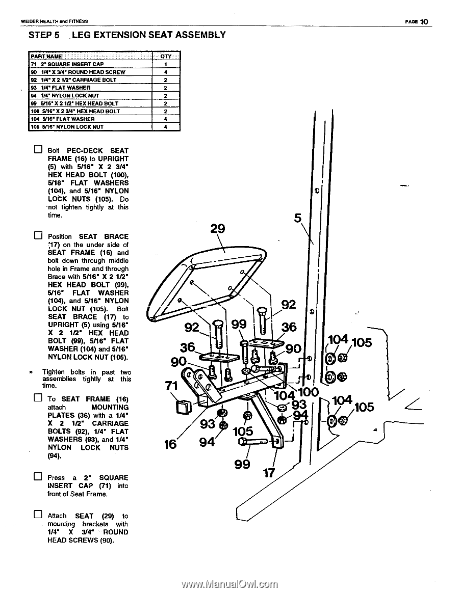
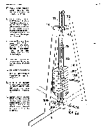
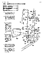
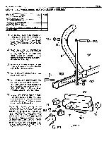
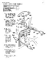
WEIDER HEALTH and FITNESS STEP 5 LEG EXTENSION SEAT ASSEMBLY PART NAME 71 2" SQUARE INSERT CAP 90 VC X 3/4" ROUND HEAD SCREW 92 1/4' X 21/2' CARRIAGE BOLT 93 1/4' FLAT WASHER 94 1/4" NYLON LOCK NUT 99 5/16" X 21/2' HEX HEAD BOLT 100 5/16" X 23/4' HEX HEAD BOLT 104 5/16* FLAT WASHER 105 5/16' NYLON LOCK NUT QTY 1 4 2 2 2 2 2 4 4 PAGE 10 El Bolt PEC-DECK SEAT FRAME (16) to UPRIGHT (5) with 5/16" X 2 3/4' HEX HEAD BOLT (100), 5/16° FLAT WASHERS (104), and 5/16" NYLON LOCK NUTS (105). Do not tighten tightly at this time. Position SEAT BRACE 17) on the under side of SEAT FRAME (16) and bolt down through middle hole in Frame and through Brace with 5/16" X 2 1/2" HEX HEAD BOLT (99), 5/16" FLAT WASHER (104), and 5/16" NYLON LOCK NUT (lUb). bolt SEAT BRACE (17) to UPRIGHT (5) using 5/16" X 2 1t2" HEX HEAD BOLT (99), 5/16' FLAT WASHER (104) and 5/16" NYLON LOCK NUT (105). Tighten bolts in past two assemblies tightly at this time. To SEAT FRAME (16) attach MOUNTING PLATES (36) with a 1/4" X 2 1/2" CARRIAGE BOLTS (92), 1/4' FLAT WASHERS (93), and 1/4" NYLON LOCK NUTS (94). Press a 2" SQUARE INSERT CAP (71) into front of Seat Frame. El Attach SEAT (29) to mounting brackets with 1/4' X 3/4' ROUND HEAD SCREWS (90). 29 N 92 36 90 41.1 0 71 93 16 94 1792 I II 36 d'd 11(90 3') 104105 104100 „ V 1 4 93 Tvgf105 si 105 4 99 17
-
 1
1 -
2
-
3
-
4
-
 5
5 -
 6
6 -
 7
7 -
 8
8 -
 9
9 -
 10
10 -
 11
11 -
 12
12 -
 13
13 -
 14
14 -
 15
15 -
16
-
17
-
18
-
19
-
20
-
21
-
22
-
23
-
24
 |
 |