Weider 8920 English Manual - Page 6
Arm Assembly - weight system
 |
View all Weider 8920 manuals
Add to My Manuals
Save this manual to your list of manuals |
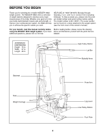
Page 6 highlights
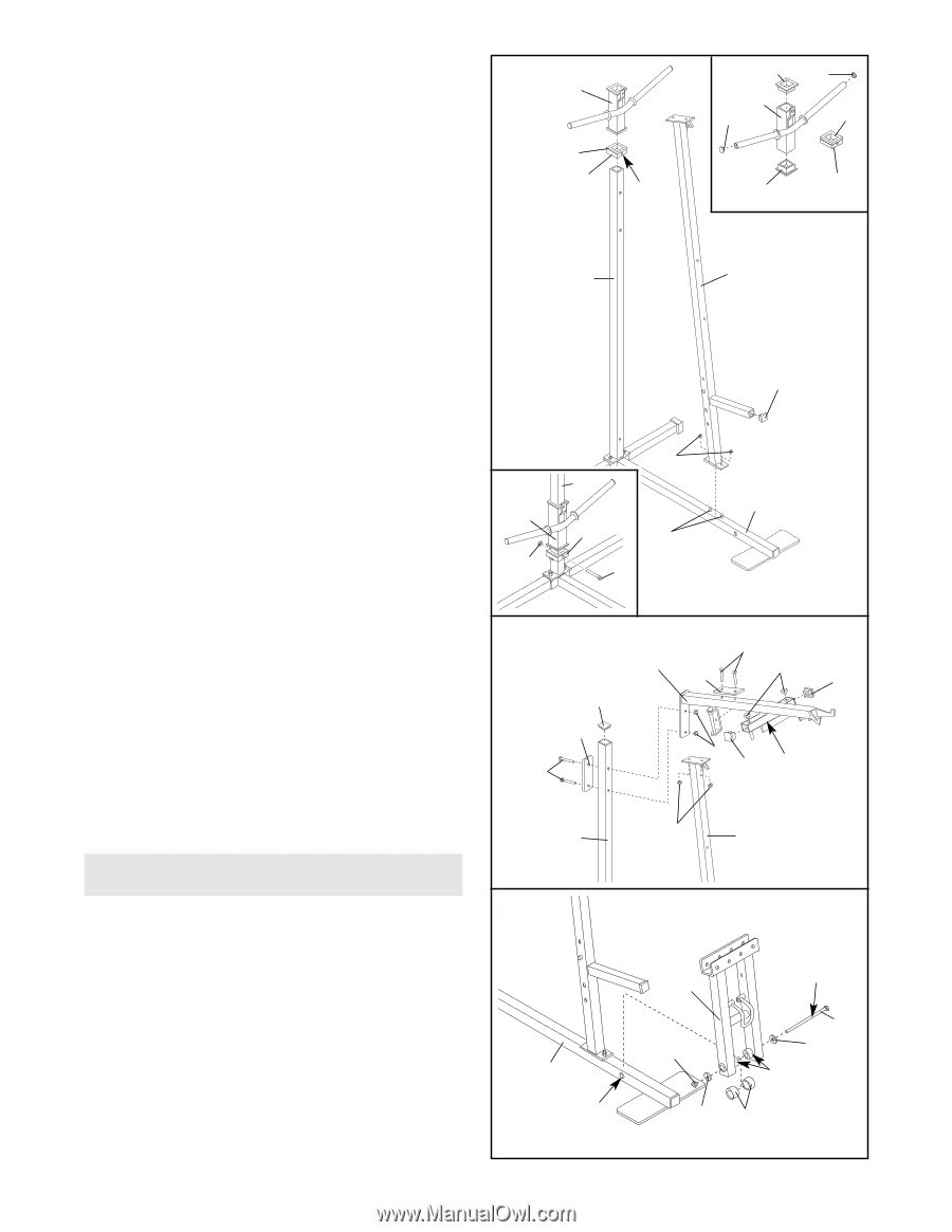
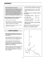
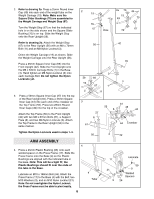
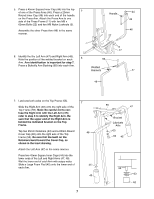
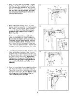
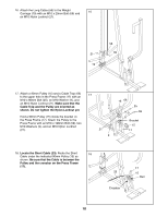
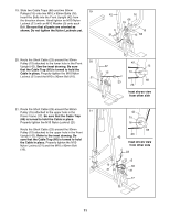
2. Refer to drawing 2a. Press a 25mm Round Inner Cap (49) into each end of the weight tube on the 2 Weight Carriage (19). Note: Make sure the Square Slider Bushings (70) are assembled to the Weight Carriage and Weight Stop (67). Turn the Weight Stop (67) so that the indicated hole is on the side shown and the Square Slider Bushing (70) is on top. Slide the Weight Stop onto the Rear Upright (56). 2a 70 49 19 19 49 70 70 67 Hole 70 67 Refer to drawing 2b. Attach the Weight Stop (67) to the Rear Upright (56) with an M8 x 70mm 56 42 Bolt (11) and an M8 Nylon Locknut (3). Orient the Weight Carriage (19) as shown. Slide the Weight Carriage onto the Rear Upright (56). Press a 25mm Square Inner Cap (65) into the Front Upright (42). Slide the Front Upright onto the M8 x 63mm Carriage Bolts (1) in the Base (4). Hand tighten an M8 Nylon Locknut (3) onto each Carriage Bolt. Do not tighten the Nylon Locknuts yet. 3. Press a 50mm Square Inner Cap (27) into the top of the Rear Upright (56). Press a 45mm Square Inner Cap (44) into each end of the crossbar on the Top Frame (55). Press two 25mm Round Inner Caps (49) into the top of the crossbar. Attach the Top Frame (55) to the Front Upright (42) with two M8 x 67mm Bolts (61), a Support Plate (8), and two M8 Nylon Locknuts (3). Attach the Top Frame to the Rear Upright (56) in the same manner. 65 3 2b 56 4 19 67 1 3 11 3 27 8 61 61 55 8 49 44 3 44 Crossbar Tighten the Nylon Locknuts used in steps 1-3. 56 3 42 ARM ASSEMBLY 4 4. Press a 25mm Plastic Bushing (26) onto each welded spacer on the Press Frame (17). Slide the Press Frame onto the Base (4) so the Plastic Bushings are aligned with the indicated tube in the base. Note: This will be a tight fit; the Plastic Bushings should fit over the ends of the tube in the Base. Lubricate an M10 x 198mm Bolt (59). Attach the Press Frame (17) to the Base (4) with the Bolt, two M10 Washers (9), and an M10 Nylon Locknut (21). Note: Do not overtighten the Nylon Locknut; the Press Frame must be able to pivot easily. 6 4 Tube 17 21 9 Lubricate 59 9 Welded Spacers 26
-
 1
1 -
 2
2 -
 3
3 -
 4
4 -
 5
5 -
 6
6 -
 7
7 -
 8
8 -
 9
9 -
 10
10 -
 11
11 -
 12
12 -
13
-
14
-
15
-
16
-
17
-
18
-
19
-
20
-
21
-
22
-
23
-
24
-
25
-
26
-
27
 |
 |