Weider Cross Bow By 1500x Canadian English Manual - Page 12
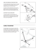
Locate the two Short Cables 33.
 |
View all Weider Cross Bow By 1500x manuals
Add to My Manuals
Save this manual to your list of manuals |
Page 12 highlights
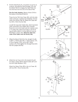
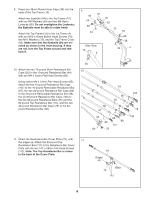
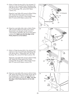
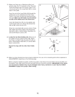
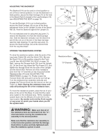
23. Make sure there are no Resistance Bars (not shown) under the "U"-channels on the 10-pound Center Resistance Bar (not shown). Have a second person pull on the Long Cable (80) to create slack in the Cable. Insert the end of the Long Cable (80) through the welded tube on the indicated end of the Cross Tube (11) and then through the remaining Swivel Arm (22). Make sure the Cable is on the indicated side of the welded rod in the Swivel Arm. Insert the Swivel Arm (22) into the welded tube on the Cross Tube (11). Secure the Swivel Arm with an M4 x 5mm Screw (107). Wrap the Long Cable (80) around a 90mm Pulley (28). Attach the Pulley inside of the Swivel Arm (22) with an M10 x 42mm Button Head Bolt (71) and an M10 Nylon Locknut (76). 23 71 Rod 22 107 80 28 76 11 24. Locate the two Short Cables (33). Wrap one of 24 the Cables around a 90mm Pulley (28). Attach the Pulley to a High Pulley Housing (21) with an M10 x 42mm Button Head Bolt (71) and an M10 Nylon Locknut (76). Repeat this step with the other Short Cable (33). 76 21 71 28 33 25. Make sure that all parts have been properly tightened. The use of the remaining parts will be explained in ADJUSTMENTS, beginning on the following page. Before using the resistance system, pull the long cable a few times to be sure that it moves smoothly over the pulleys. If the cable does not move smoothly, find and correct the problem. IMPORTANT: If the cables are not properly installed, they may be damaged when heavy resistance is used. See the CABLE DIAGRAM on page 16 for proper cable routing. 12
-
 1
1 -
2
-
3
-
4
-
5
-
6
-
 7
7 -
 8
8 -
 9
9 -
 10
10 -
 11
11 -
 12
12 -
 13
13 -
 14
14 -
 15
15 -
 16
16 -
 17
17 -
18
-
19
-
20
-
21
-
22
-
23
 |
 |
