Weider Pro 145 English Manual - Page 6
Assembly
 |
View all Weider Pro 145 manuals
Add to My Manuals
Save this manual to your list of manuals |
Page 6 highlights
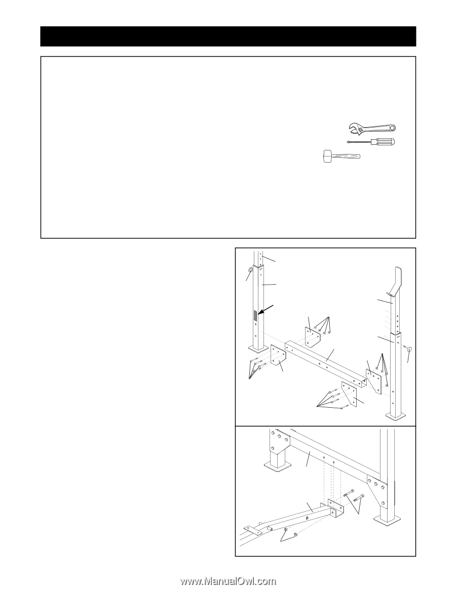
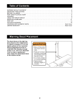
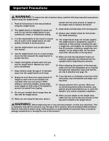
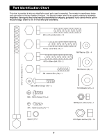
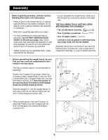
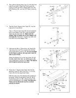
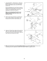
Assembly Before beginning assembly, carefully read the following information and instructions: ¥ Place all parts of the weight bench in a cleared area and remove the packing materials; do not dispose of the packing materials until assembly is completed. ¥ Read each assembly step before you begin. ¥ For help identifying the small parts used in assembly, use the PART IDENTIFICATION CHART on the previous page. Note: Some small parts may have been pre-attached for shipping purposes. If a part is not in the parts bag, check to see if it has been pre-attached. ¥ Tighten all parts as you assemble them, unless instructed to do otherwise. ¥ As you assemble the weight bench, make sure that all parts are oriented as shown in the drawings. THE FOLLOWING TOOLS (NOT INCLUDED) ARE REQUIRED FOR ASSEMBLY: ¥ Two (2) adjustable wrenches ¥ One (1) phillips screwdriver ¥ One (1) rubber mallet ¥ Lubricant, such as grease or petroleum jelly, and soapy water will also be needed. Assembly will be more convenient if you have the following tools: A socket set, a set of open-end or closed-end wrenches, or a set of ratchet wrenches. 1. Before assembling this weight bench, be sure that you have read and understand the information in the box above. The help of another person is recommended for assembly. Position the Crossbar (3) as shown. Attach the Crossbar to each Upright Base (7) with four M10 x 81mm Bolts (35), a Support Plate (20), and four M10 Nylon Locknuts (19). Note the position of the warning decal and make sure the Upright Bases are oriented exactly as shown. Slide the Uprights (1) into the Upright Bases (7) and secure them at the desired height with two M10 x 67mm Adjustment Knobs (30). 2. While another person holds the Crossbar (3), attach the Frame (2) to the Crossbar with two M10 x 81mm Bolts (35) and two M10 Nylon Locknuts (19). 1 1 30 7 Warning Decal 20 19 3 20 35 35 2 3 1 7 19 20 30 20 2 35 19 6
-
 1
1 -
 2
2 -
 3
3 -
 4
4 -
 5
5 -
 6
6 -
 7
7 -
 8
8 -
 9
9 -
 10
10 -
 11
11 -
 12
12 -
13
-
14
-
15
-
16
 |
 |