Weider Pro 455 English Manual - Page 6
Assembly
 |
View all Weider Pro 455 manuals
Add to My Manuals
Save this manual to your list of manuals |
Page 6 highlights
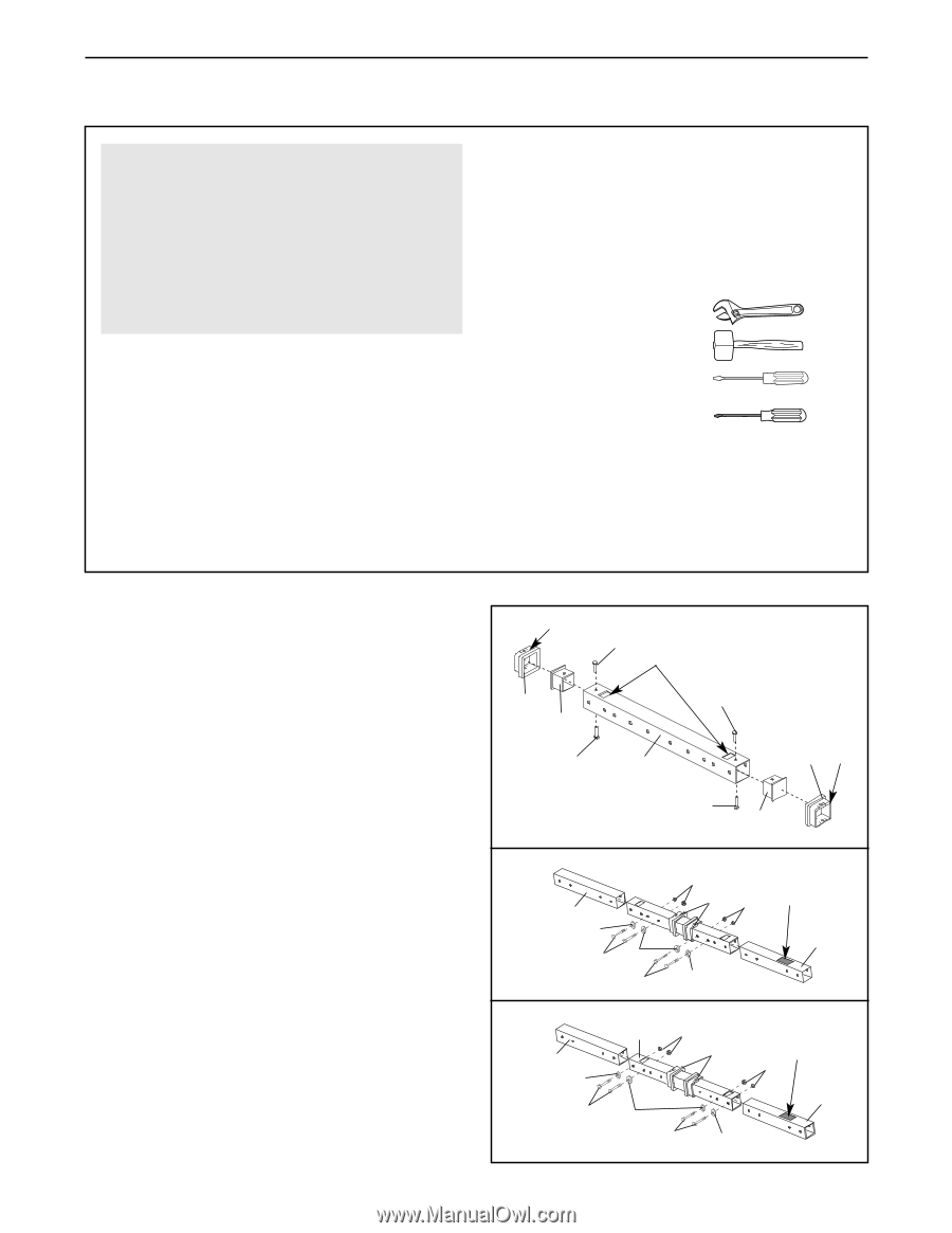
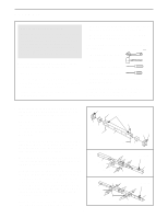
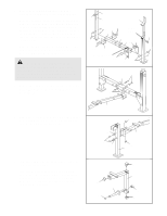
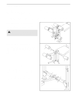
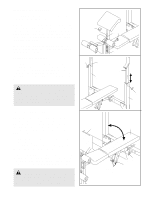
ASSEMBLY Make Things Easier for Yourself Everything in this manual is designed to ensure that the weight bench can be assembled successfully by anyone. However, it is important to realize that the versatile weight bench has many parts and that the assembly process will take time. Most people find that by setting aside plenty of time, assembly will go smoothly. Before beginning assembly, carefully read the following information and instructions: • Assembly requires two people. • Place all parts in a cleared area and remove the packing materials. Do not dispose of the packing materials until assembly is completed. • Tighten all parts as you assemble them, unless instructed to do otherwise. • As you assemble the weight bench, make sure all parts are oriented as shown in the drawings. • For help identifying small parts, use the PART IDENTIFICATION CHART on page 5. The following tools (not included) are required for assembly: • Two adjustable wrenches • One rubber mallet • One standard screwdriver • One Phillips screwdriver • Lubricant, such as grease or petroleum jelly, and soapy water. Assembly will be more convenient if you have a socket set, a set of open-end or closed-end wrenches, or a set of ratchet wrenches. 1. Note: The parts shown in this step may be preassembled. Also, the Extension Tubes (43, see step 2) may be slid onto the Crossbar (3). 1 Tab 34 Holes Slide an Extension Tube Bushing (45) onto each end of the Crossbar (3) as shown. Press a Crossbar 45 34 Bushing (46) into each end of the Crossbar. Secure 46 the two Crossbar Bushings with four M4 x 16mm Screws (34). 34 3 45 Tab Note: The tabs on the Extension Tube Bushings (45) will need to be pushed into the holes in the Crossbar (3) when the Extension Tubes (43, see step 2) are slid onto the Crossbar. 2a 2. The weight bench can be adjusted for use with either a standard barbell (see drawing 2a) or an Olympic barbell (see drawing 2b). Note the position of the warning decal and make sure that the Extension Tubes (43) are oriented as shown. Slide an Extension Tube onto one end of the Crossbar (3) and over an Extension Tube 2b Bushing (45). Align the indicated holes and secure the Extension Tube to the Crossbar with two M10 x 68mm Bolts (44), two M10 Washers (24), and two M10 Nylon Locknuts (19). Attach the other Extension Tube (43) to the other end of the Crossbar (3) in the same manner. 6 34 46 43 24 44 24 44 19 Warning 45 19 Decal 43 24 43 24 44 3 19 45 24 44 24 Warning Decal 19 43
-
 1
1 -
 2
2 -
 3
3 -
 4
4 -
 5
5 -
 6
6 -
 7
7 -
 8
8 -
 9
9 -
 10
10 -
 11
11 -
 12
12 -
13
-
14
-
15
-
16
 |
 |