Weider Weevsy3426 Uk Manual - Page 12
Arm Assembly
 |
View all Weider Weevsy3426 manuals
Add to My Manuals
Save this manual to your list of manuals |
Page 12 highlights
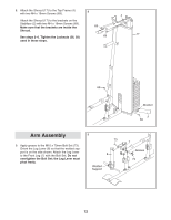
8. Attach the Shroud (17) to the Top Frame (4) with two M4 x 19mm Screws (69). 8 4 Attach the Shroud (17) to the brackets on the Stabilizer (2) with two M4 x 19mm Screws (69). Make sure that the brackets are inside the 69 Shroud. See steps 2-6. Tighten the Locknuts (56, 58) 69 17 used in these steps. 69 Bracket 2 69 Arm Assembly 9. Apply grease to the M10 x 70mm Bolt Set (73). Orient the Leg Lever (8) so that the welded support is on the side shown. Attach the Leg Lever to the Front Leg (7) with the Bolt Set. Do not overtighten the Bolt Set; the Leg Lever must pivot freely. 9 73 8 Welded Support 7 Grease 73 12
-
 1
1 -
2
-
3
-
4
-
5
-
6
-
 7
7 -
 8
8 -
 9
9 -
 10
10 -
 11
11 -
 12
12 -
 13
13 -
 14
14 -
 15
15 -
 16
16 -
 17
17 -
18
-
19
-
20
-
21
-
22
-
23
-
24
-
25
-
26
-
27
-
28
-
29
-
30
-
31
-
32
 |
 |
12
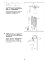
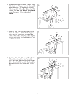
8.
Attach the Shroud (17) to the Top Frame (4)
with two M4 x 19mm Screws (69).
Attach the Shroud (17) to the brackets on the
Stabilizer (2) with two M4 x 19mm Screws (69).
Make sure that the brackets are inside the
Shroud.
See steps 2–6. Tighten the Locknuts (56, 58)
used in these steps.
8
69
69
17
4
69
69
Bracket
2
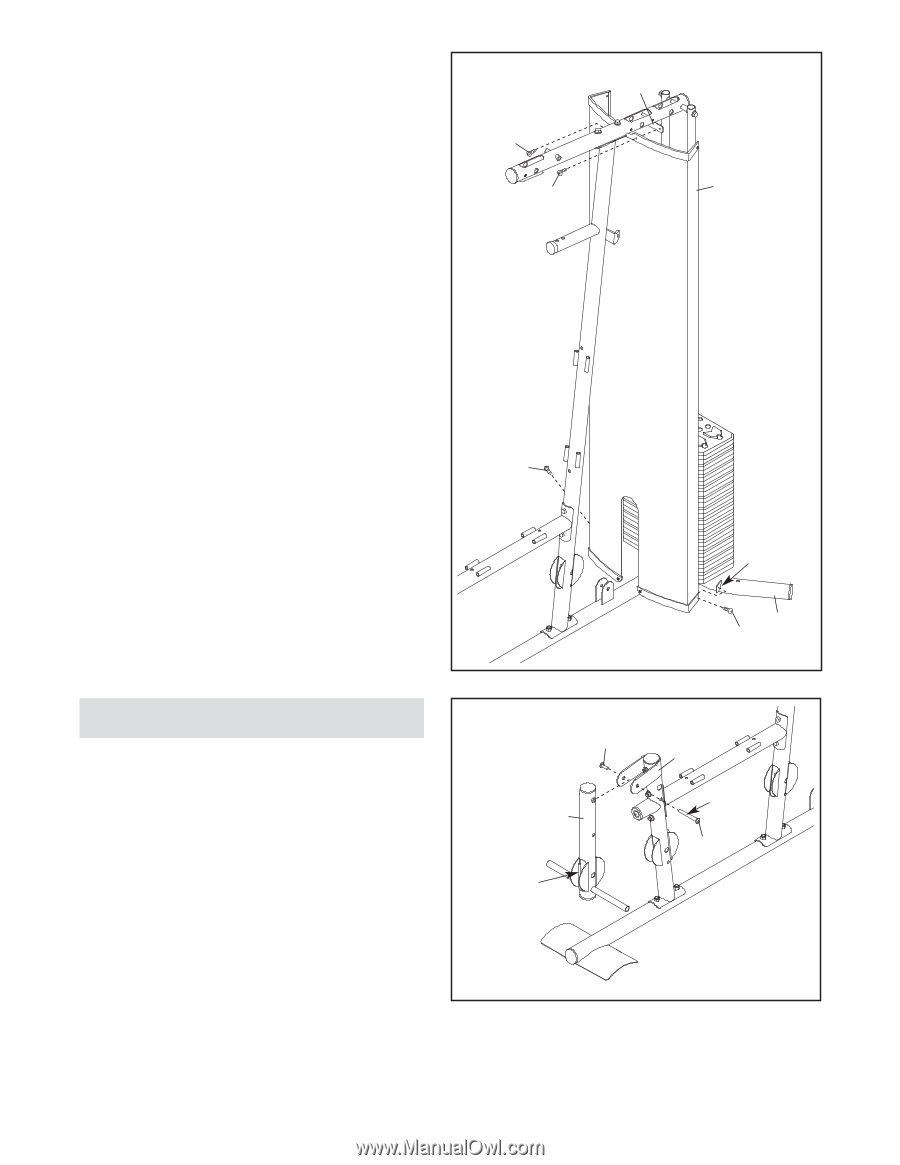
9.
Apply grease to the M10 x 70mm Bolt Set (73).
Orient the Leg Lever (8) so that the welded sup-
port is on the side shown. Attach the Leg Lever
to the Front Leg (7) with the Bolt Set.
Do not
overtighten the Bolt Set; the Leg Lever must
pivot freely.
9
73
73
Grease
Welded
Support
7
8
Arm Assembly