Weider Xr20 English Manual - Page 6
Frame Assembly - weights
 |
View all Weider Xr20 manuals
Add to My Manuals
Save this manual to your list of manuals |
Page 6 highlights
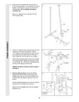
2. Slide the Front Upright (42) onto the 5/16Ó x 2 2 1/2Ó Carriage Bolts (1) in the Base (4). Hand tighten a 5/16Ó Nylon Locknut (3) onto each Carriage Bolt. Do not tighten the Nylon Locknuts yet. Press a 1Ó Square Inner Cap (65) into the Front Upright (42). FRAME ASSEMBLY 42 65 3 4 1 3. Press a 2Ó Square Inner Cap (27) into the indicated end of the Top Frame (55). Press a 1 3/4Ó Square Inner Cap (44) into each end of the crossbar on the Top Frame. Press two 1Ó Inner Caps (84) into the top of the crossbar. Attach the Top Frame (55) to the Front Upright (42) and the Rear Upright (56) with four 5/16Ó x 2 3/4Ó Bolts (11), four 5/16Ó Flat Washers (8), and four 5/16Ó Nylon Locknuts (3). Tighten all Nylon Locknuts used in steps 1 through 3. 3 27 3 4. See the inset drawing. Press two Weight 4 Inserts (87) into the top of each of the nine Weights (25). Be sure that each Weight is ori- ented so that the large pin groove is on the bottom. Set two Weight Bumpers (19) onto the indicated bracket on the Base (4) as shown. 25 Stack the nine Weights (25) onto the Weight Bumpers (19). 11 8 55 56 44 3 25 87 11 8 84 44 Crossbar 42 Pin Groove 19 Large Pin Groove 4 6
-
 1
1 -
 2
2 -
 3
3 -
 4
4 -
 5
5 -
 6
6 -
 7
7 -
 8
8 -
 9
9 -
 10
10 -
 11
11 -
 12
12 -
13
-
14
-
15
-
16
-
17
-
18
-
19
-
20
-
21
-
22
-
23
-
24
-
25
-
26
-
27
-
28
-
29
 |
 |
