Weslo Cadence 40.8treadmill English Manual - Page 6
Extension Leg 34 with a Handrail Bolt 91, a Handrail
 |
View all Weslo Cadence 40.8treadmill manuals
Add to My Manuals
Save this manual to your list of manuals |
Page 6 highlights
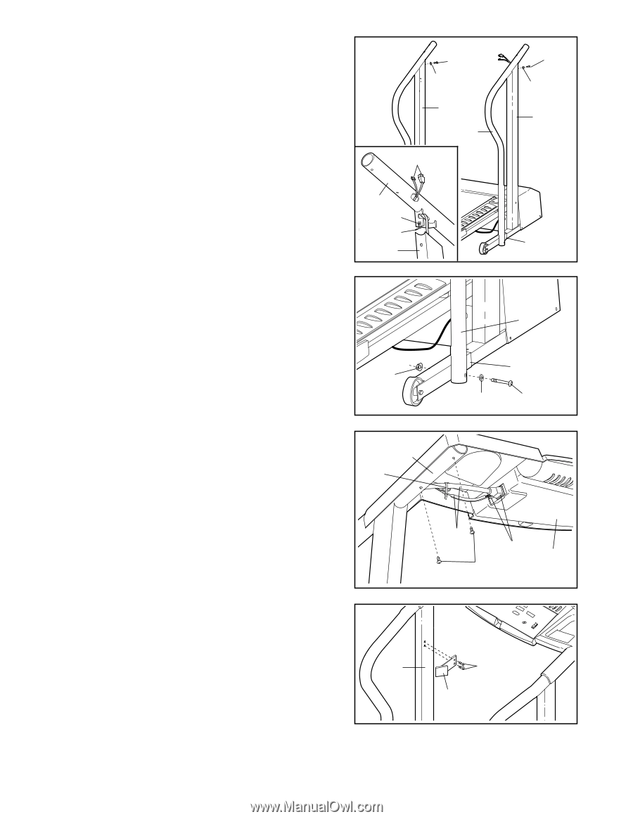
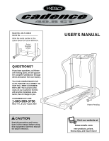
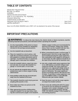
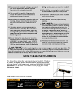
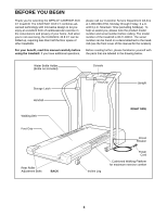
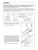
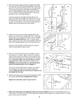
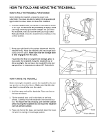
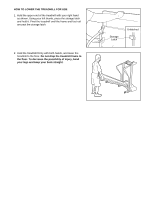
3. Refer to the inset drawing. If there is a plastic tie holding the Cage Nut (70) in the Right Handrail (88), remove the plastic tie. Feed the Wire Harness (21) in the right Upright (11) through the bracket on the Right Handrail (88) as shown. Using needlenose pliers, grip one of the connectors on the Wire Harness and pull the Wire Harness up through the hole in the Right Handrail. Insert the bracket on the Right Handrail (88) into the upper end of the right Upright (11), with the lower end of the Right Handrail on the side of the Extension Leg (34) as shown. Hand tighten a Short Handrail Bolt (89) with a Washer (39) into the upper end of the Upright. 4. Attach the lower end of the Right Handrail (88) to the Extension Leg (34) with a Handrail Bolt (91), a Handrail Washer (92), and a Handrail Nut (93) as shown. Do not tighten the Handrail Bolt yet. Note: It may be necessary to push on the lower end of the Handrail to align the hole in the Handrail with the hole in the Extension Leg. Attach the Left Handrail to the left Extension Leg (not shown) as described in steps 3 and 4. 3 89 39 11 88 21 88 70 Tie 11 4 89 39 11 34 88 34 93 92 91 5. Place the Console Base (46) on the Uprights (11) (the left Upright is not shown). Make a loop in the indicated cable tie and insert the two Wires (21) through the loop. Connect the two Wires to the connectors in the Console Base. Important: Make sure that the Wires are fully inserted. Pull the cable tie tight and cut off the end. WARNING: Do not disconnect or connect the Wires while the treadmill power cord is plugged in. Thread four Screws (80) into the Uprights (11) and the Console Base (46). After all four Screws have been started, tighten the Screws until they are snug; do not overtighten the Screws. 6. Attach the Storage Latch (14) to the left Upright (11) with two Screws (80). Do not overtighten the Screws. Tighten all of the bolts used in steps 3 and 4. 5 11 Cable Tie 6 11 21 Connectors 46 80 80 14 7. Make sure that all parts are tightened before you use the treadmill. Keep the included allen wrench in a secure place. The allen wrench is used to adjust the walking belt (see page 13). To protect the floor or carpet, place a mat under the treadmill. 6
-
 1
1 -
 2
2 -
 3
3 -
 4
4 -
 5
5 -
 6
6 -
 7
7 -
 8
8 -
 9
9 -
 10
10 -
 11
11 -
 12
12 -
13
-
14
-
15
-
16
-
17
-
18
-
19
 |
 |