Weslo Cadence 55 Treadmill English Manual - Page 8
How To Change The Incline Of The Tread, Mill
 |
View all Weslo Cadence 55 Treadmill manuals
Add to My Manuals
Save this manual to your list of manuals |
Page 8 highlights
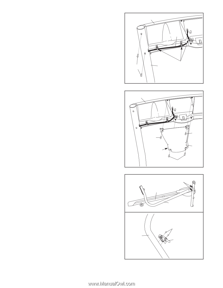
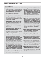
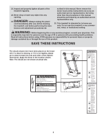
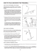
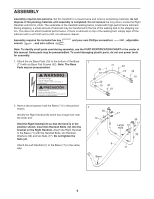
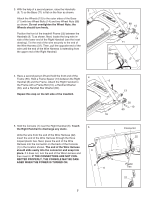
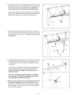
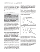
6. Set the Console (1) on the Right Handrail (6) and the Left Handrail (not shown). Finger tighten four Console Screws 6 1 (70) (only two are shown) into the Console. After you have started all four Console Screws, tighten them. Insert the excess Wire Harness (22) down into the Right 22 Handrail (6). Tighten the three plastic ties around the Wire Harness, and then cut off the ends of the plastic ties. Plastic 70 6 Ties 7. Attach the Console Back (4) to the Console (1) with four 16mm Screws (58). Note that there is a slot in the side of 7 1 the Console Back for the wire-make sure that no wires are pinched. 58 Slot 58 4 58 8. Carefully lower the Handrails (6, 7) to the floor. Center the Frame (55) between the Handrails, and tighten the four Handrail Bolts (12). Then, raise the Handrails to the vertical position. See drawing 8a. Attach the Storage Latch Assembly (41) to the Left Handrail (7) with two 16mm Screws (58). Make sure that the Storage Latch Assembly is oriented as shown. See HOW TO CHANGE THE INCLINE OF THE TREADMILL on page 11. Adjust the incline legs and insert the incline pins into the incline legs. 9. Make sure that all parts are properly tightened before you use the treadmill. Keep the included hex key in a secure place. The hex key is used to adjust the walking belt (see page 14). To protect the floor or carpet, place a mat under the treadmill. 8 8a 7 12 55 6, 7 58 41 8
-
 1
1 -
2
-
 3
3 -
 4
4 -
 5
5 -
 6
6 -
 7
7 -
 8
8 -
 9
9 -
 10
10 -
 11
11 -
 12
12 -
 13
13 -
14
-
15
-
16
-
17
-
18
-
19
 |
 |