Weslo Cadence 800 Treadmill Uk Manual - Page 8
Damaged When The Power Is Turned On.
 |
View all Weslo Cadence 800 Treadmill manuals
Add to My Manuals
Save this manual to your list of manuals |
Page 8 highlights
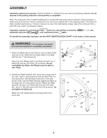
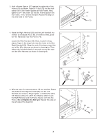
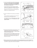
6. Carefully pull the opposite end of the tape to pull the Wire Harness (60) up through the Right Handrail (59) and out of the hole in the side of the Right Handrail. Remove the tape from the Wire Harness (60). 6 60 Tape 59 7. Orient the Crossbar (91) with the large hole at the right of the smaller hole as shown. Set the Crossbar against the Handrails (53, 59) with the brackets on the Crossbar aligned with the two small holes in each Handrail. Attach the Crossbar with two Crossbar Star Washers (93) and two Crossbar Screws (92). Do not tighten the Crossbar Screws yet. With the help of as second person, hold the console assembly near the Crossbar (91). Connect the pulse wire from the Crossbar to the pulse wire from the console assembly. The connectors should slide easily into each other and snap into place. If they do not slide easily and snap into place, turn a connector and then insert it. Insert the ground wire through the two plastic ties shown in step 8. Attach the end of the ground wire to the small hole in the side of the Right Handrail (59) with a Silver Ground Screw (69). 7 Console Assembly 53 Ground 69 Wire 93 91 92 Pulse Wires 93 59 92 8. Place the Console Base (52) on the Crossbar (91), Right Handrail (59) and the Left Handrail (not shown). Be careful not to pinch any wires. Attach the Console Base with four 3/4" Screws (2) (only two Screws are shown). Do not overtighten the Screws. Insert the Wire Harness (60) through the two indicated plastic ties on the Console Base (52). Next, touch the Right Handrail (59) to discharge any static. See the inset drawing. Insert the connector on the end of the Wire Harness into the red socket beneath the console. The connector should slide easily into the socket and snap into place. If the connector does not slide easily and snap into place, turn the connector and then insert it. Make sure that the connector and wire appear as shown in the inset drawing. IF THE CONNECTORS ARE NOT INSERTED PROPERLY, THE CONSOLE MAY BE DAMAGED WHEN THE POWER IS TURNED ON. 8 52 60 2 59 Ties 91 60 Socket 8
-
 1
1 -
2
-
 3
3 -
 4
4 -
 5
5 -
 6
6 -
 7
7 -
 8
8 -
 9
9 -
 10
10 -
 11
11 -
 12
12 -
 13
13 -
14
-
15
-
16
-
17
-
18
-
19
-
20
-
21
-
22
-
23
-
24
 |
 |
