Weslo Cadence C42 Treadmill English Manual - Page 6
Hold the Console 10 near the Console Base 46. Insert - treadmill
 |
View all Weslo Cadence C42 Treadmill manuals
Add to My Manuals
Save this manual to your list of manuals |
Page 6 highlights
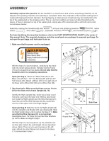
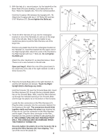
3. With the help of a second person, tip the treadmill so the Base Pads (40) (see drawing 1) are laying flat on the floor. Raise the Uprights (62, 76) to the vertical position. Hold the Crossbar (34) between the Uprights (62, 76). Attach the Crossbar with two 2 1/2" Bolts (53) and two 5/16" Washers (57). Do not tighten the Bolts yet. 3 53 57 34 76 62 57 53 4. Feed the Wire Harness (21) up into the rectangular bracket on one of the Handrails (1) and out of the large hole in the left side. Note: It may be helpful to use needlenose pliers to pull the Wire Harness out of the large hole. Remove any plastic ties from the rectangular bracket on the Handrail (1). Insert the bracket into the upper end of the Right Upright (62). Attach the ends of the Handrail to the Right Upright with two 1" Bolts (8). Do not tighten the Bolts yet. Attach the other Handrail (1) as described above. Note: There is not a wire harness on the left side. Open part bag C. Attach the end of the ground wire to the small hole in the side of the right Handrail (1) with a Silver Screw (70). 4 1 8 5. Place the Console Base (46) on the right Handrail (1) and the left Handrail (not shown). Touch the Right Upright (62) to discharge any static. Hold the Console (10) near the Console Base (46). Insert the Wire Harness (21) through the two indicated plastic ties on the Console Base. Next, insert the Wire Harness up through the indicated opening in the Console Base and through the plastic tie on the bottom of the Console. Locate the two connectors on the Wire Harness (21). Plug the wider connector into the connector labeled A in the drawing at the right. The connectors should slide together easily and snap into place (see drawing 5a). If they do not, turn the connector on the Wire Harness and try again. Plug the other connector on the Wire Harness into the connector labeled B (see drawing 5b). IF THE CONNECTORS ARE NOT INSERTED PROPERLY, THE CONSOLE MAY BE DAMAGED WHEN THE POWER IS TURNED ON. Securely tighten the plastic tie on the Console (10) to prevent the Wire Harness (21) from slipping. Then, cut off the end of the plastic tie. 6 5 46 1 62 8 Ground Wire 21 70 Large Hole 1 76 62 8 Bracket 8 10 A Tie 21 B 5a A 21 Ties 21 5b B 21
-
 1
1 -
 2
2 -
 3
3 -
 4
4 -
 5
5 -
 6
6 -
 7
7 -
 8
8 -
 9
9 -
 10
10 -
 11
11 -
 12
12 -
13
-
14
-
15
-
16
-
17
-
18
-
19
 |
 |
