Weslo Cadence C6 Treadmill Uk Manual - Page 10
Aged When The Power Is Turned On.
 |
View all Weslo Cadence C6 Treadmill manuals
Add to My Manuals
Save this manual to your list of manuals |
Page 10 highlights
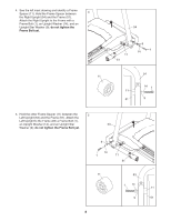
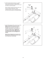
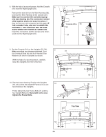
8. With the help of a second person, hold the Console 8 (91) near the Right Upright (54). Remove the wire tie from the Wire Harness (98). Connect the Wire Harness to the console wire. Make sure to connect the connectors properly (see drawing 8a). The connectors should slide together easily and snap into place. If they do not, turn one connector and try again. IF THE CONNECTORS ARE NOT CONNECTED PROPERLY, THE CONSOLE MAY BE DAMAGED WHEN THE POWER IS TURNED ON. Insert the connectors and the excess wire downward into the Right Upright (54). 91 Console Wire 8a 98 54 98 9. Set the Console (91) on the Uprights (53, 54). 9 Make sure that no wires are pinched. Start 91 four Handrail Bolts (8) with four Handrail Star Washers (5) into the Uprights as shown. With the help of a second person, carefully lower the Uprights (53, 54) to the floor. 8 5 54 10. See the lower drawing. Position the Uprights 10 (53, 54) so that the treadmill Frame (51) is cen- tered between the Uprights. Firmly tighten the two Frame Bolts (1) and the four Upright Bolts (2). Be careful not to overtighten the Frame Bolts. 8 5 53 1 2 51 Top View 54 51 53 10
-
 1
1 -
2
-
3
-
4
-
 5
5 -
 6
6 -
 7
7 -
 8
8 -
 9
9 -
 10
10 -
 11
11 -
 12
12 -
 13
13 -
 14
14 -
 15
15 -
16
-
17
-
18
-
19
-
20
-
21
-
22
-
23
-
24
-
25
-
26
-
27
-
28
 |
 |
