Weslo Cadence C66 Treadmill English Manual - Page 7
Right Handrail 47.
 |
View all Weslo Cadence C66 Treadmill manuals
Add to My Manuals
Save this manual to your list of manuals |
Page 7 highlights
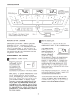
6. Touch the Right Upright (62) to discharge any static. Insert the connector on the end of the Wire Harness (21) into the socket beneath the console. The connector should slide easily into the socket and snap into place. If the connector does not slide easily and snap into place, turn the connector and then insert it. Make sure that the connectors and wires appear as shown in drawing 6a. 6 Ties 21 10 Next, insert the excess Wire Harness (21) down through the opening in the Console Base (46). See the inset draw- ing in step 5. Securely tighten the plastic tie on top of the Console Base to prevent the Wire Harness from slipping. Then, cut off the end of the plastic tie. See drawing 6b. Press the Bookrack (90) onto the Console Base in 97 47 62 13 97 the location shown. 6a 6b Set the Console (10) on the Console Base (46). Insert the ex- cess Wire Harness (21) into the large hole in the side of the Right Handrail (47). Securely tighten the plastic ties on the bottom of the Console Base to prevent the Wire Harness from slipping. Then, cut off the ends of the plastic ties. 21 Connector 46 Attach the Console (10) to the Console Base (46) with four 1/2" Screws (97) and two 3/4" Screws (13). Start all six 7 Screws before tightening any of them; do not over- tighten the Screws. 62, 76 7. Lower the Uprights (62, 76) until the Handrails (47) are touching the floor. See the lower drawing. Position the Uprights (62, 76) so the treadmill Frame (75) is centered between them. Firmly tighten the four 2 1/4" Bolts (78) and all other bolts and screws used in assembly steps 3, 4, 5, and 6. 47 Top View 46 97 13 90 78 62 76 75 8. Attach the Storage Latch (14) to the left Upright (76) with two 3/4" Screws (13). Be careful not to overtighten the Screws. 8 1 14 13 76 9. Make sure that all parts are properly tightened before you use the treadmill. Note: Extra hardware may be included. Keep the included allen wrenches in a secure place; the large allen wrench is used to adjust the walking belt (see page 14). To protect the floor or carpet, place a mat under the treadmill. 7
-
 1
1 -
 2
2 -
 3
3 -
 4
4 -
 5
5 -
 6
6 -
 7
7 -
 8
8 -
 9
9 -
 10
10 -
 11
11 -
 12
12 -
13
-
14
-
15
-
16
-
17
-
18
-
19
 |
 |
